Hybrid energy-storage DC micro grid hierarchical control method

A DC micro-grid and hybrid energy storage technology, applied in the energy industry, single-network parallel feeding arrangements, sustainable manufacturing/processing, etc., can solve problems such as voltage fluctuations, complex reaction mechanisms, and complex communication networks, and maintain stability , communication is simple, and the effect of maintaining power balance

Inactive Publication Date: 2016-02-03
SHAANXI REGIONAL ELECTRIC POWER GROUP +1
View PDF6 Cites 54 Cited by
  • Summary
  • Abstract
  • Description
  • Claims
  • Application Information

AI Technical Summary

Problems solved by technology

[0007] The master-slave control method relies too much on the stable operation of the main converter. Once the main converter fails, the reaction mechanism is more complicated; the voltage droop control method, when the grid power fluctuates, there will be voltage fluct

Method used


Image

  • Hybrid energy-storage DC micro grid hierarchical control method
  • Hybrid energy-storage DC micro grid hierarchical control method
  • Hybrid energy-storage DC micro grid hierarchical control method

Examples


Embodiment 1

[0040] Example 1: Division of operating states of a hybrid DC microgrid

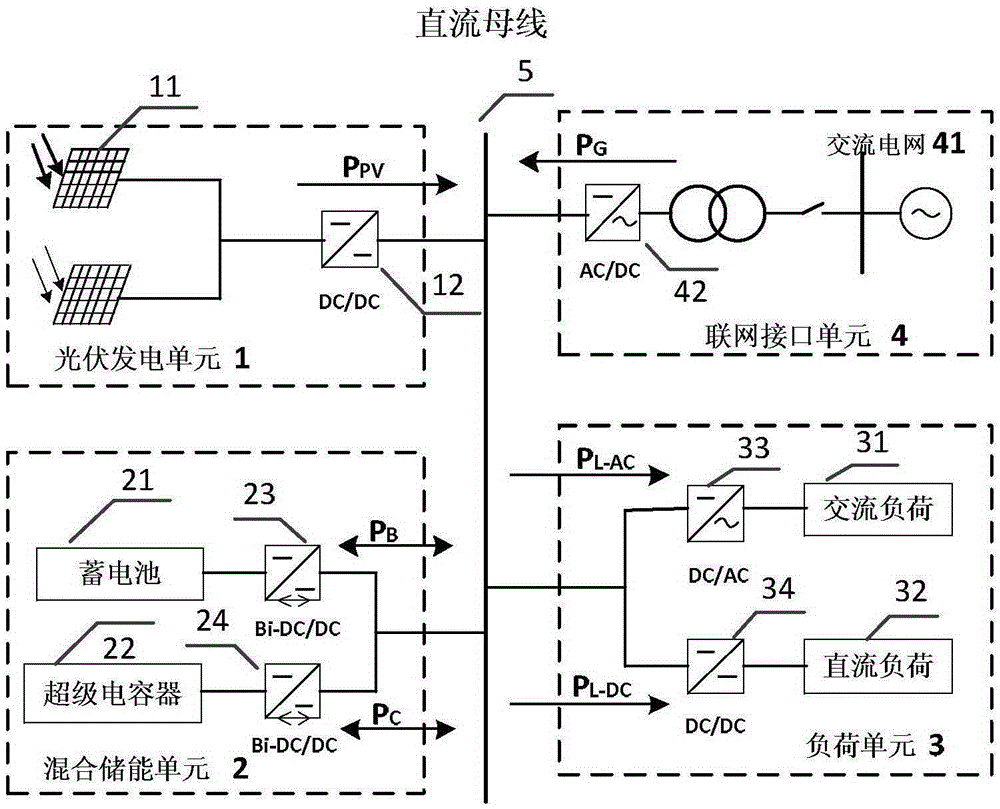
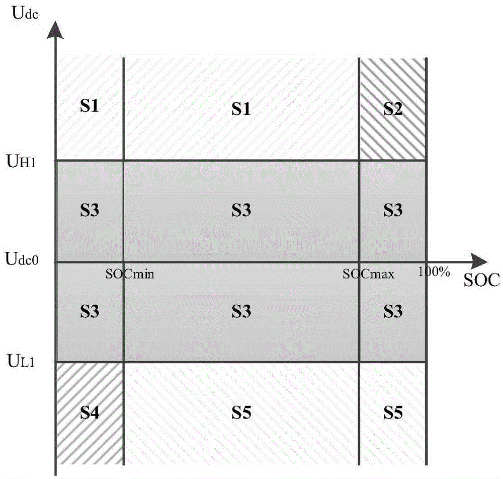
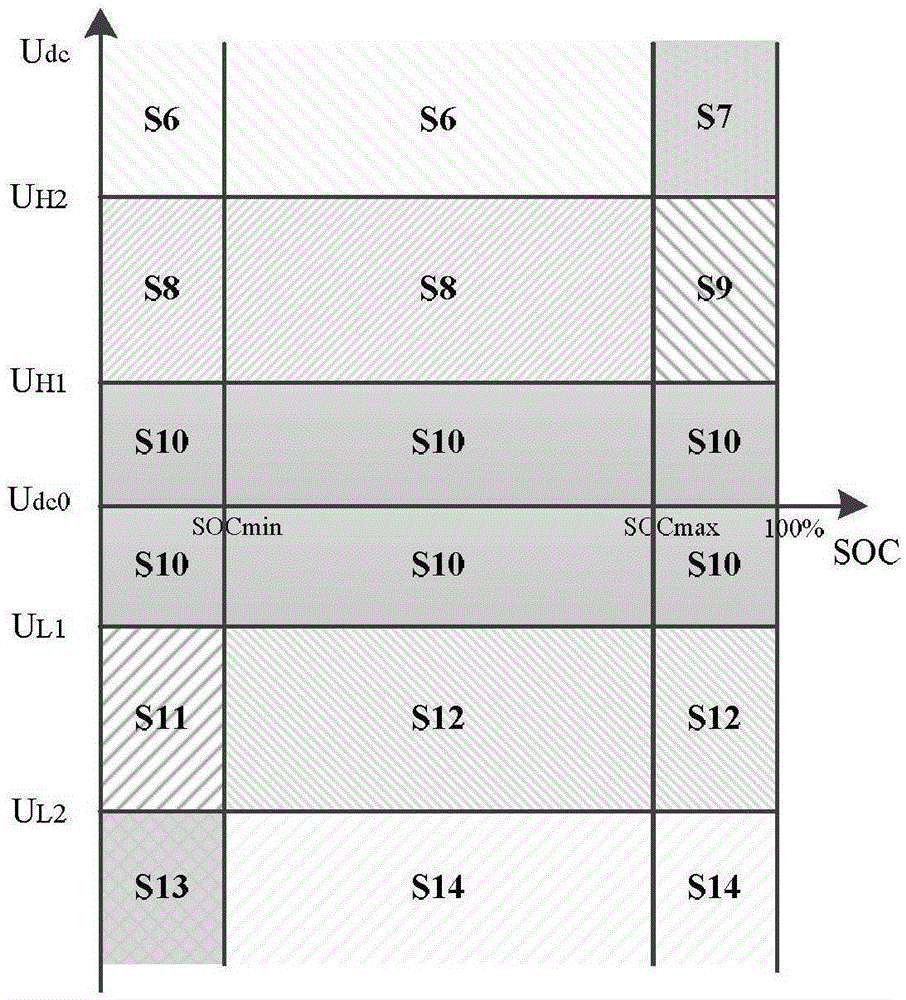
[0041] There are many components in the DC microgrid and various operating modes, so the control of the microgrid needs to detect the operating status of the microgrid in real time. In Embodiment 1 of the present invention, the parameter G of the networked operation mode is collected flag , DC bus voltage U dc and battery state of charge SOC (StateofCharge) and other parameters to divide the working state of the DC microgrid

[0042] 1) Networking operation mode parameters

[0043] Define the DC microgrid networking operation mode parameter G flag , when G flag When it is 1, it means that the microgrid is in the network operation mode. When G flag When it is 0, the microgrid is in the island operation mode.

[0044] When the DC microgrid is connected to the AC main grid, and the bus voltage is stable, the power injected by the AC main grid into the DC microgrid is:

[0045] P G =P Load -P PV -P...

Embodiment 2

[0064] see image 3 , using a layered control method to control the DC microgrid, which is divided into a system control layer and a converter control layer according to different control tasks and control objects.

[0065] Wherein, the system control layer includes a central controller 6, which collects network operation mode parameters G flag , DC bus voltage U dc Judging the current operating mode of the DC microgrid based on the state of charge SOC of the battery, for example, judging the current operating mode of the DC microgrid according to Table 1, so as to give the control mode of each unit of the DC microgrid, and send a control command to the converter control layer, To control the work of the converter and coordinate the working modes of each unit.

[0066] Inverter controller, including each inverter, the inverter receives control instructions from the central controller, selects the corresponding control mode, generates a driving signal that can act on the inve...


PUM


Abstract

The invention discloses a hybrid energy-storage DC micro grid hierarchical control method. The DC micro grid comprises a photovoltaic power generation unit, a hybrid energy storage unit, a load unit, a networking interface unit and a DC bus, wherein each unit is connected with the DC bus respectively. By adopting the hierarchical control method, a system control layer and a current converter control layer are used for controlling the DC micro grid, the system control layer acquires networking operation mode parameters, DC bus voltage and a battery charge state to judge the current operation mode of the DC micro grid, a control mode of each unit of the DC micro grid is given, and a control instruction is sent to the current converter control layer. Each current converter can adjust the self control mode according to a different DC micro grid operation state, network voltage stability and power balance can be maintained effectively, and relative to master-slave control, excessive dependence on the master current converter is reduced; relative to a multi-agent control mode, communication is simpler; and relative to a voltage sag control mode, the network voltage is more stable and controllable.

Description

technical field [0001] The present application relates to a power grid control method, in particular, to a hierarchical control method for a hybrid energy storage direct current microgrid. Background technique [0002] In order to alleviate the tense situation of energy supply and reduce greenhouse gas emissions, distributed generation (Distributed Generation, DG) represented by photovoltaic and wind power generation has gradually attracted attention. However, there are problems such as intermittency and instability in the distributed power supply itself. In order to realize the flexible and efficient utilization of DG in the medium and low voltage range, the distributed power supply, load, energy storage device and control system are combined and controlled through the controllable interface. The microgrid system connected with the large power grid has emerged as the times require. [0003] The main goal of DC microgrid operation control is to maintain the power balance of...

Claims


Application Information

Patent Timeline
IPC IPC(8): H02J3/38H02J7/35
CPCY02P80/14
Inventor 岳青
Owner SHAANXI REGIONAL ELECTRIC POWER GROUP
Why Eureka
Try Eureka