Structure of micro device of microfluidic chip series

A technology for microfluidic chips and microdevices, applied in fluid controllers, instruments, laboratory utensils, etc., can solve the problems of glass chip development limitations, inability to manufacture pump valve systems, and unsatisfactory cost and service life.

Active Publication Date: 2016-02-24
XIAMEN XINCHUANG BIOLOGICAL TECH
View PDF3 Cites 8 Cited by
  • Summary
  • Abstract
  • Description
  • Claims
  • Application Information

AI Technical Summary

Problems solved by technology

The advantage of the diaphragm pump (diaphragmpump) is that it works reliably and powerfully, similar to a mechanical pump, but its disadvantages are also obvious. For example, it is necessary to use a variable material as a diaphragm, so that it is impossible to avoid the possible contamination or interference of this material to the system. In addition, the diaphragm The complexity of the pump province makes the manufacturing cost and life unsatisfactory
[0005] Therefore, the existing key technologies of micro-fluidic chips such as micro-valve and micro-pump have the above defects, especially for glass chips (with the best optical quality and chemical quality), since glass is an indeformable hard It is impossible to manufacture built-in pump and valve systems on glass chips, which greatly restricts the further development of glass chips.

Method used


Image

  • Structure of micro device of microfluidic chip series
  • Structure of micro device of microfluidic chip series
  • Structure of micro device of microfluidic chip series

Examples


Embodiment Construction

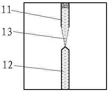
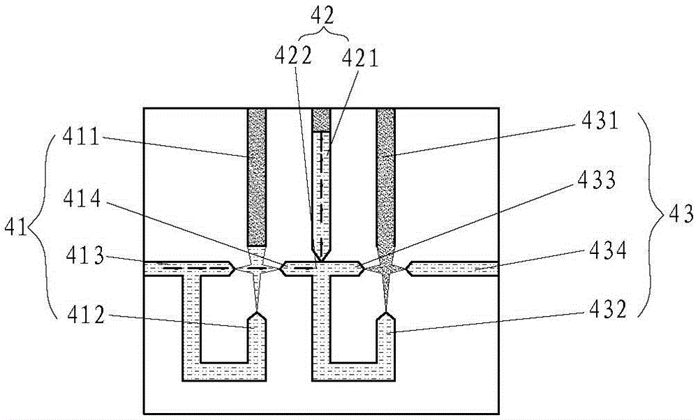
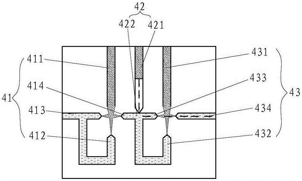
[0028] The present invention discloses a microfluidic chip series microdevice. In terms of structural design, the series microdevice includes a gas channel and at least one liquid channel, and the gas channel and each liquid channel are communicated through microchannels (capillary tubes).

[0029] The theoretical basis of the present invention is: there is a definite relationship between the pressure difference of the gas-liquid interface in the gas-liquid two-phase and the moving direction of the gas-liquid interface in the microchannel, and the purpose of two aspects can be achieved by using this relationship: A gas -The movement of the liquid interface can reflect the pressure difference between the gas-liquid two phases; B controls the movement of the gas-liquid interface by controlling the pressure difference between the gas-liquid two phases.

[0030] The following will be described with specific examples.

[0031] See Figure 1a to Figure 1c is a schematic diagram of a...


PUM


Abstract

The invention discloses a structure of a micro device in a microfluidic chip series. The structure comprises a gas channel and at least one liquid channel. The gas channel is communicated with the liquid channels through microchannels. The micro device is a micro piston and comprises a gas channel and a liquid channel, wherein one end of the gas channel is connected with gas, the other end of the gas channel is communicated with the middle segment of the liquid channel through a gradually-narrowed microchannel, and the two ends of the liquid channel are connected with liquid. The structure is controlled by a pressure digitized gas micro circuit in a chip, a gas phase and a liquid phase are isolated by micro holes, no movable component exists, no special breathable or elastic material is needed, and the pressure difference of the gas phase and the liquid phase is used for driving a gas-liquid interface so that the micro device can have the functions of pressure sensing, fluid passage opening and closing, effective power conveying of liquid and the like. One-time etching forming can be achieved on hard materials such as glass, and a large number of micro devices can be conveniently integrated with low cost.

Description

[0001] The present invention is a divisional application with filing date: 2010-09-14, application number: 201080069777.3 (PCT application number: PCT / CN2010 / 076904), and name: "Structure of a microfluidic chip series microdevice". technical field [0002] The invention relates to the technical field of micro-fluidic chip manufacturing, in particular to the micro-piston structure of the micro-device of the micro-fluidic chip series. Background technique [0003] Lab on a chip (Labonachip) is a rapidly developing technology that can be widely used in laboratory research and daily medical testing in various fields such as life sciences, chemistry and physics. Microfluidic (also called microfluidic in China) chip (Microfluidicchip) technology is the backbone technology in the chip laboratory. Since microfluidics are the carriers of substances in the lab-on-a-chip (such as various dissolved compounds in the aqueous phase, cells in the culture medium, etc.), how to control the ...

Claims


Application Information

Patent Timeline
Patent Type & Authority Applications(China)
IPC IPC(8): F04B9/12F04B19/00B01L3/00F16K99/00G01N13/02
CPCB01L3/50273B01L3/502738B01L3/502746B01L2200/0621B01L2200/14B01L2300/0816B01L2300/0861B01L2300/0887B01L2400/0487B01L2400/0688B01L2400/082F04B9/08F04B9/12F04B19/006F04F1/18F16K99/0017F16K99/0021F16K99/0057F16K2099/0084F16K2099/0094G01N13/02G01N35/10G01N35/1074G01N35/1097
Inventor 彭兴跃
Owner XIAMEN XINCHUANG BIOLOGICAL TECH
Why Eureka
Try Eureka