
Pyrolysis and gasification garbage incinerator adopting oxygen enriched combustion technique

A waste incinerator, pyrolysis gasification technology, applied in the field of pyrolysis gasification waste incinerator, can solve the problems that it is difficult to ensure the decomposition of harmful substances such as dioxin, the temperature of the second combustion chamber is lowered, and the operation is not ideal , to achieve the effects of full combustion, improved combustion conditions, and miniaturization

Active Publication Date: 2016-02-24
HUAZHONG UNIV OF SCI & TECH
View PDF6 Cites 4 Cited by
  • Summary
  • Abstract
  • Description
  • Claims
  • Application Information

AI Technical Summary

Problems solved by technology

[0005] 1) When dealing with garbage with high water content, the actual operation is not ideal
my country's domestic waste has complex components, high water content, and low calorific value. The calorific value of combustible gas produced after garbage pyrolysis is low and unstable. It is difficult to maintain the temperature of the second combustion chamber at a relatively high temperature only by combusting combustible gas. In the process, a large amount of auxiliary fuel such as diesel oil is often required, which greatly increases the operating cost
[0006] 2) The above-mentioned problems will be more serious due to lack of oxygen when conventional pyrolysis gasification incinerators operate in plateau areas
The oxygen content in the air in the plateau area is low. In order to ensure complete combustion, more air needs to be blown in than in the plain area. This will greatly reduce the temperature of the second combustion chamber, making it difficult to ensure the decomposition of harmful substances such as dioxins.

Method used


Image

  • Pyrolysis and gasification garbage incinerator adopting oxygen enriched combustion technique
  • Pyrolysis and gasification garbage incinerator adopting oxygen enriched combustion technique

Examples


Embodiment Construction

[0027] In order to make the object, technical solution and advantages of the present invention clearer, the present invention will be further described in detail below in conjunction with the accompanying drawings and embodiments. It should be understood that the specific embodiments described here are only used to explain the present invention, not to limit the present invention. In addition, the technical features involved in the various embodiments of the present invention described below can be combined with each other as long as they do not constitute a conflict with each other.

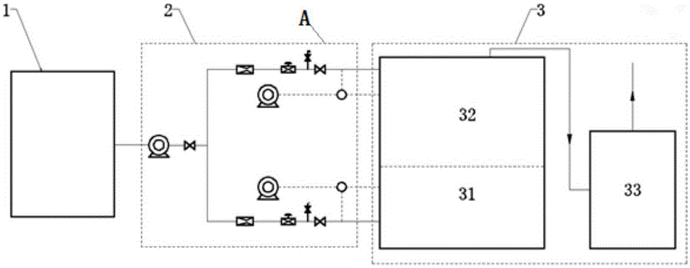
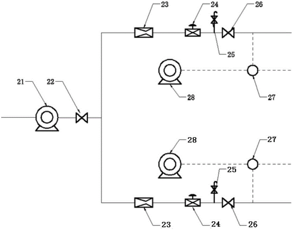
[0028] refer to figure 1 , figure 2 , a pyrolysis gasification waste incinerator using oxygen-enriched combustion technology, characterized in that it includes an oxygen preparation unit 1, an oxygen injection unit 2 and an incinerator main unit 3, wherein,

[0029] An oxygen preparation unit 1, which is used to generate oxygen-enriched gas and inject the generated oxygen-enriched gas into th...


PUM


Abstract

The invention discloses a pyrolysis and gasification garbage incinerator adopting an oxygen enriched combustion technique. The pyrolysis and gasification garbage incinerator comprises an oxygen preparation unit, an oxygen injection unit and an incinerator main body unit, wherein the oxygen injection unit is connected with the oxygen preparation unit and the incinerator main body unit, the oxygen injection unit comprises a booster fan, a shutoff valve and two oxygen flow control devices, and each oxygen flow control device comprises a flow meter, a regulating valve, a stop valve, a mixer and an air supply fan; the shutoff valve is connected with the flow meters; the incinerator main body unit comprises an incinerator body and a smoke purification device, and the incinerator body comprises a first combustion chamber, a second combustion chamber and a partition. According to the pyrolysis and gasification garbage incinerator, the problems of low combustion temperature and combustion efficiency, substandard pollutant discharge and the like caused by low oxygen content of air or low garbage calorific value can be effectively solved.

Description

technical field [0001] The invention belongs to the field of incinerators, and more specifically relates to a pyrolysis gasification garbage incinerator adopting oxygen-enriched combustion technology. Background technique [0002] In recent years, with the rapid development of the economy and the gradual improvement of people's living standards, the problem of domestic waste in my country has become more and more serious. Many large and medium-sized cities are facing the dilemma of "garbage besieged". And there is also the problem of domestic waste disposal in tourist spots. At present, the two main garbage disposal methods in our country are landfill and incineration. The composting method has higher requirements on garbage components and organic matter content, so it is rarely used. The landfill method has a simple process and low investment cost, and has been widely used in my country. However, in recent years, as my country's land resources have become more and more scar...

Claims


Application Information

Patent Timeline
IPC IPC(8): F23G5/027F23G5/16F23L7/00F23G5/50
CPCF23G5/027F23G5/165F23G5/50F23L7/007Y02E20/34
Inventor 张世红廖新杰潘浩刘英鹏邵敬爱王贤华杨海平陈汉平
Owner HUAZHONG UNIV OF SCI & TECH
Learn More