Array substrate, display panel and display device
A technology of array substrates and substrates, which is applied in the direction of electrical components, electric solid-state devices, circuits, etc., and can solve problems such as affecting TFT characteristics, display quality degradation, and difficulty in removal
- Summary
- Abstract
- Description
- Claims
- Application Information
AI Technical Summary
Problems solved by technology
Method used
Image
Examples
Embodiment 1
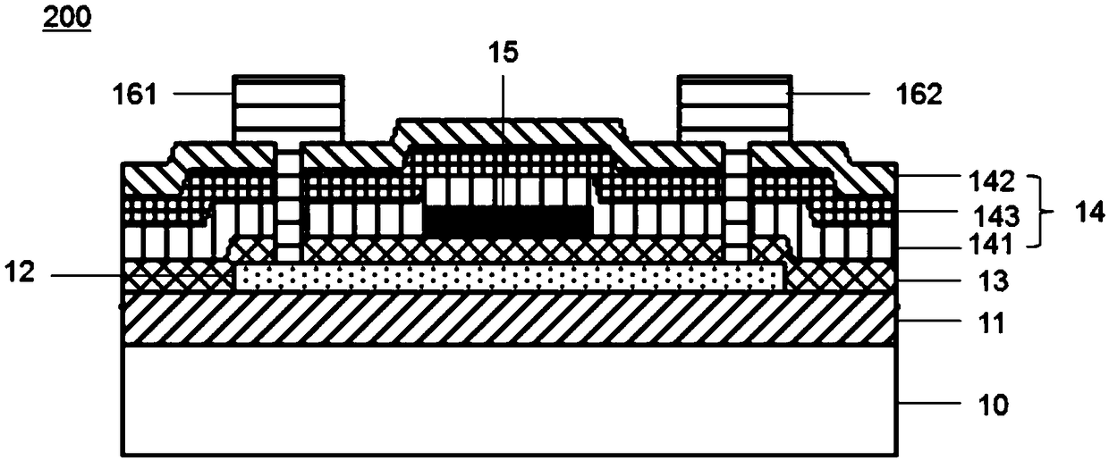
[0029] Please refer to figure 2 , figure 2 A partial cross-sectional view of an array substrate 200 provided by an embodiment of the present invention. The array substrate 200 includes a substrate 10, and a buffer layer 11, a semiconductor layer 12, a gate insulating layer 13, a gate electrode 15, an interlayer insulating layer 14, and a source electrode 161 arranged in sequence in a direction perpendicular to the substrate 10. and drain electrode 162 .
[0030] The substrate 10 is mainly made of glass, but it can also be curved transparent plastic, such as polyimide. If curved transparent plastic is used as the material of the substrate 10, polyimide with excellent heat resistance can be used in consideration of the process of performing high-temperature deposition on the substrate 10 (polyimide can withstand high temperatures. ).
[0031] The buffer layer 11 includes a fourth silicon nitride layer and a second silicon oxide layer (not shown in the figure) stacked, and ...
Embodiment 2
[0040] Please refer to Figure 6 , Figure 6 A partial cross-sectional view of another array substrate 300 provided in an embodiment of the present invention. The structure of the array substrate 300 in this embodiment is basically the same as that of the array substrate 200 in Embodiment 1, except that the interlayer insulating layer 14 includes first A silicon nitride layer 141 , a second silicon nitride layer 143 , a first silicon oxide layer 142 and a third silicon nitride layer 144 . The relative dielectric constant of the third silicon nitride layer 144 is greater than or equal to 6.5, which can reduce the damage and charge injection to the underlying interlayer insulating layer caused by the electric field generated during film formation, etching and cleaning.
Embodiment 3
[0042] Please refer to Figure 7 , Figure 7 It is a schematic structural diagram of a display panel 20 provided by an embodiment of the present invention. The display panel 20 includes an array substrate 21 , an opposite substrate 23 opposite to the array substrate 21 , and a liquid crystal layer 22 located between the array substrate 21 and the opposite substrate 23 . Wherein, the array substrate 21 is the array substrate described in the above-mentioned embodiments.
[0043] The display panel provided in this embodiment adopts the array substrates of the above-mentioned embodiments, and the interlayer insulating layer of the array substrate at least includes a first silicon nitride layer, a silicon nitride layer, The second silicon nitride layer and the first silicon oxide layer, and the hydrogen atom percentage content of the first silicon nitride layer is greater than the hydrogen atom percentage content of the second silicon nitride layer, effectively avoiding the firs...
PUM
 Abstract
Description
Claims
Application Information
 - R&D
- Intellectual Property
- Life Sciences
- Materials
- Tech Scout
- Unparalleled Data Quality
- Higher Quality Content
- 60% Fewer Hallucinations
Browse by: Latest US Patents, China's latest patents, Technical Efficacy Thesaurus, Application Domain, Technology Topic, Popular Technical Reports.
© 2025 PatSnap. All rights reserved.Legal|Privacy policy|Modern Slavery Act Transparency Statement|Sitemap|About US| Contact US: help@patsnap.com


