Exhaust gas treatment equipment

A technology for treating device and waste gas, applied in the combustion method, combustion type, incinerator, etc., can solve the problem of difficult and harmless, and achieve the effect of reliable high temperature, reliable combustion, and improved cooling efficiency

Active Publication Date: 2016-02-24
KOIKE SANSO KOGYO CO LTD
View PDF7 Cites 5 Cited by
  • Summary
  • Abstract
  • Description
  • Claims
  • Application Information

AI Technical Summary

Problems solved by technology

In this case, there is a concern that it may be difficult to sufficiently detoxify

Method used


Image

  • Exhaust gas treatment equipment
  • Exhaust gas treatment equipment
  • Exhaust gas treatment equipment

Examples


Embodiment Construction

[0034] Hereinafter, the processing device of the present invention will be described. The processing device of the present invention uses silane, disilane, diborane, phosphine, arsenic trihydride, nitrogen trifluoride, silicon fluoride, and silicon chloride generated from the manufacturing process of semiconductors, liquid crystal panels, or solar cells. Exhaust gases such as toxic special material gases, carbon tetrafluoride, sulfur hexafluoride, etc., which have a negative impact on the global environment, and explosive hydrogen gas are burned or decomposed to be harmless and discharged.

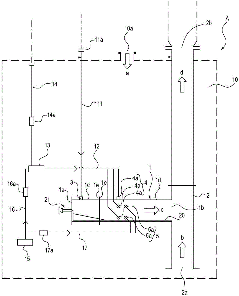
[0035] The processing device of the present invention is configured to supply exhaust gas that needs to be harmless and supply combustion-supporting gas into the combustion chamber, and ignite the burner to keep the combustion chamber at a high temperature, thereby enabling the supplied exhaust gas to burn without Or decompose and become harmless at high temperature. In addition, the process...


PUM


Abstract

To provide exhaust gas treatment equipment for removing an exhaust gas by burning or pyrolyzing the same in a rational manner. Treatment equipment (A) having: a combustion chamber (1) for removing a supplied exhaust gas by burning or decomposing the same, one end part (1a) of the combustion chamber (1) being closed; an exhaust pipe (2) for discharging the removed exhaust gas and connected to an other end part (1b) of the combustion chamber (1); and a housing (10) for accommodating the combustion chamber (1) and the exhaust pipe (2). In the combustion chamber, an exhaust gas supply port (3) for supplying the exhaust gas to be removed to the closed one end part (1a) side is provided, a burner (4) is provided closer to the exhaust pipe (2) side than is the exhaust gas supply port (3), and a combustion-sustaining gas supply nozzle (5) for supplying a combustion-sustaining gas is provided between the burner (4) and the exhaust gas supply port (3), or is provided closer to the exhaust pipe (2) side than is the burner (4).

Description

Technical field [0001] The present invention relates to an exhaust gas treatment device used to detoxify and discharge exhaust gas discharged from, for example, a semiconductor manufacturing process by burning or thermally decomposing it. Background technique [0002] For example, it is known that a specific process in a semiconductor manufacturing process generates a gas that is toxic to the human body and a gas that has a negative impact on the global environment. When releasing such harmful gases into the atmosphere, removal and detoxification of toxic substances are required. Therefore, an exhaust gas treatment device that can satisfy the above-mentioned requirements by burning or decomposing such exhaust gas has been proposed (for example, refer to Patent Documents 1 and 2). [0003] The exhaust gas treatment device described in Patent Document 1 has: a cylindrical combustion chamber, one end of the combustion chamber is blocked, and the exhaust gas and reaction promotion gas...

Claims


Application Information

Patent Timeline
Patent Type & Authority Applications(China)
IPC IPC(8): F23G7/06F23J1/06
CPCF23G5/32F23G7/065F23J1/06
Inventor 金丙哲藤森一彰森山优星野铁郎藤木亮马育新小池哲夫
Owner KOIKE SANSO KOGYO CO LTD
Why Eureka
Try Eureka