Power module

A power module and power switch technology, which is applied to output power conversion devices, semiconductor/solid-state device components, semiconductor devices, etc., can solve the problems of large freewheeling circuit inductance, large freewheeling circuit area, and low reliability of modules , to achieve the effects of reducing stray inductance and switching loss, reducing the area of ​​the freewheeling circuit, and improving reliability

Active Publication Date: 2016-03-02
YANGZHOU GUOYANG ELECTRONICS CO LTD
View PDF6 Cites 2 Cited by
  • Summary
  • Abstract
  • Description
  • Claims
  • Application Information

AI Technical Summary

Problems solved by technology

[0003] However, as the power switch in the module is switched repeatedly, the inductance generated by its structural configuration will reduce the reliability of the power module
Due to the large area of ​​the freewheeling circuit of the traditional power module, the inductance of the freewheeling circuit of the module is large, which causes the switching loss of the module to be large and the reliability is low

Method used


Image

  • Power module
  • Power module
  • Power module

Examples


Embodiment Construction

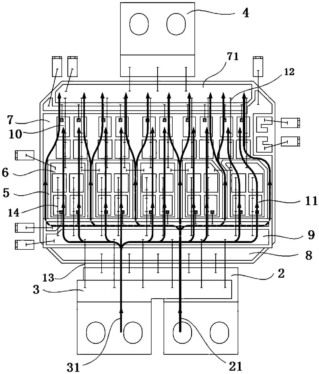
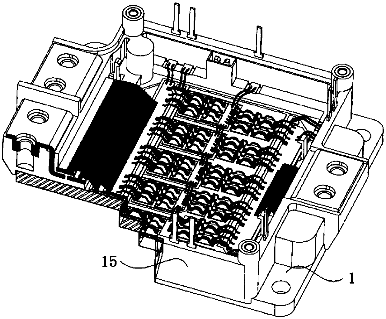
[0019] Such as figure 1 As shown, a power module includes a base plate 1, a positive electrode 2, a negative electrode 3, an output electrode 4, and an insulating substrate arranged on the base plate 1, and the positive electrode 2, the negative electrode 3, and the output electrode 4 are connected to the base plate 1. An insulating layer is provided. In this embodiment, the insulating layer is image 3 In the insulating shell 15 shown in , the insulating substrate includes a thermally conductive insulating layer and a copper layer formed on the thermally conductive insulating layer, and a plurality of mutually independent annular insulating grooves 5 are arranged on the copper layer of the insulating substrate. The embodiment of the present invention By etching a plurality of mutually independent annular insulating grooves 5 on the copper layer of the insulating substrate. The copper layer inside each insulating slot is the copper layer 6 of the lower arm, and the copper lay...


PUM


Abstract

The invention discloses a power module. The power module comprises a bottom plate, a positive electrode, a negative electrode, an output electrode and an insulating substrate arranged on the bottom plate; an insulating layer is arranged between the positive electrode, the negative electrode and the output electrode, and the bottom plate separately; the insulating substrate comprises a thermal conducting insulating layer and copper layers formed in the thermal conducting insulating layer; a plurality of mutually-independent annular insulating grooves are formed in the copper layers of the insulating substrate; the copper layer surrounded by each insulating groove is a lower bridge arm copper layer; the copper layer on the outer side of the insulating grooves is an upper bridge arm copper layer; the upper bridge arm copper layer is provided with an upper bridge arm chip unit; the lower bridge arm copper layer is provided with a lower bridge arm chip unit; a wiring region is formed in one end, close to the positive electrode, of the upper bridge arm copper layer; a lower bridge arm source electrode line bank is arranged between the wiring region and the lower bridge arm copper layer; and the lower bridge arm source electrode line bank comprises a line bank heat conducting insulating layer and a line bank copper layer formed on the line bank heat conducting insulating layer. According to the power module, the follow current loop area is reduced, the stray inductance and the switch loss are lowered, and the reliability of the power module is improved.

Description

technical field [0001] The invention relates to the field of power electronics, in particular to a power module. Background technique [0002] The power module is a power switch module packaged by power electronic power devices such as MOS tube (metal oxide semiconductor), IGBT (insulated gate field effect transistor), and FRD (fast recovery diode) according to certain functions. Power conversion in various occasions such as automobiles, photovoltaic power generation, wind power generation, and industrial frequency conversion. [0003] However, as the power switch in the module is repeatedly switched, the inductance generated by its structural configuration can reduce the reliability of the power module. Due to the large area of ​​the freewheeling circuit of the traditional power module, the inductance of the freewheeling circuit of the module is large, which leads to large switching loss and low reliability of the module. Contents of the invention [0004] Purpose of th...

Claims


Application Information

Patent Timeline
Patent Type & Authority Applications(China)
IPC IPC(8): H01L25/11H01L23/48H02M1/00
CPCH01L2224/48139H01L2224/48472H01L2224/49111H01L2224/48227H01L2924/19107
Inventor 徐文辉王玉林滕鹤松
Owner YANGZHOU GUOYANG ELECTRONICS CO LTD
Why Eureka
Try Eureka