Jacket heat exchanger straight pipe inner pipe deep hole welding assembly device and jacket heat exchanger

A technology of heat exchangers and couplers, which is applied in the direction of indirect heat exchangers, heat exchanger types, fixed tubular conduit components, etc., and can solve problems such as difficulty in quality assurance, impossibility of grinding and inspection, and high labor intensity

Inactive Publication Date: 2016-03-16
THE CHALLENGE PETROCHEM MACHINERY CORP
View PDF13 Cites 4 Cited by
  • Summary
  • Abstract
  • Description
  • Claims
  • Application Information

AI Technical Summary

Problems solved by technology

However, the weld seam on the inner surface is ground flush with the base metal, and the base metal cannot be damaged. Since the weld seam is located at a deep position in the pipe, and is several meters or more than ten meters away from the pipe end, in the prior art, it mainly depends on manual grinding. High strength, low work efficiency, and difficult to ensure quality, especially the inner diameter of pipe fittings is usually small, and the grinding tools are limited so that grinding and inspection cannot be done

Method used


Image

  • Jacket heat exchanger straight pipe inner pipe deep hole welding assembly device and jacket heat exchanger

Examples


Embodiment 1

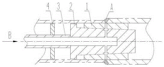
[0024] A specific embodiment of a jacketed heat exchanger straight tube inner tube deep hole welded assembly of the present application, such as figure 1 As shown, it is used for the pairing between the inner tubes of the straight tubes of the jacketed heat exchanger. The pairing device is arranged symmetrically with the center line of the tube axis. The pairing device includes a conduit 3, a tapered shaft 2 connected to the conduit 3, and The sleeve 1 matched with the taper of the taper shaft 2, the pairing device extends into the inner tube of the straight tube of the jacketed heat exchanger, under the action of external force B, the taper shaft 2 pushes the sleeve 1 to the joint of the two adjacent inner tubes Seam and expand the sleeve 1 at the same time, so that the outer surface of the sleeve 1 is close to the inner wall of the two adjacent inner tubes with straighter two adjacent inner tubes. The external force acts on the conduit 3, and the force is transmitted to the...

Embodiment 2

[0031] A specific embodiment of a jacketed heat exchanger of the present application includes a jacketed heat exchange tube composed of an inner tube and an outer tube, wherein the straight tubes and inner tubes of the jacketed heat exchanger are passed through the above-mentioned embodiment 1 The straight tube inner tube of a jacketed heat exchanger is connected by deep hole welding group to device group butt welding. The jacketed heat exchanger after butt-welding by using the pairing device has the characteristics of good welding quality, high assembly efficiency, long service life and the like.


PUM


Abstract

The invention discloses a jacket heat exchanger straight pipe inner pipe deep hole welding assembly device used for assembly between jacket heat exchanger straight pipe inner pipes. The assembly device is symmetrically arranged with respect to the center line of a pipe shaft. The assembly device comprises a guide pipe, a cone shaft connected with the guide pipe and a sleeve matched with the cone shaft in taper. The assembly device stretches into the jacket heat exchanger straight pipe inner pipes. Under the action of external force, the sleeve is pushed into a seam of the two adjacent inner pipes through the cone shaft and meanwhile expanded so as to straighten the two adjacent inner pipes, and the outer surface of the sleeve can be closely attached to the inner walls of the two adjacent inner pipes. According to a jacket heat exchanger, the straight pipe inner pipes of the jacket heat exchanger are assembled, welded and connected through the assembly device. Compared with the prior art, the problems that due to the too small inner diameter of a pipe fitting, assembly is difficult, the pipe inner surface weld reinforcement cannot be ground flat after assembly, the labor intensity of inner seam grinding is large, efficiency is low, and the grinding quality is not stable can be effectively solved. Meanwhile, the jacket heat exchanger straight pipe inner pipe deep hole welding assembly device and the jacket heat exchanger have the beneficial effects that the structure is simple, operation is easy and convenient, positioning precision is high, and repeated usage can be achieved.

Description

technical field [0001] This application relates to the technical field of precise assembly and welding of pipe fittings in petrochemical equipment, and in particular to two jacketed pipes that are suitable for use when the inner pipes of various jacketed pipes are located at deeper positions inside and require the inner pipes to have equal inner diameters and equal wall thicknesses. A jacketed heat exchanger straight tube inner tube deep hole welded coupler and a jacketed heat exchanger for segmented pipe fittings without misalignment. Background technique [0002] In petrochemical equipment, such as heating furnaces, cracking furnaces, quenching heat exchangers, and important pipe fittings, pipes, etc., it is usually required that the inner surfaces of the two pipe fittings have no misalignment after being assembled and welded. After that, the inner surface welds meet the requirements of advanced welding technology. However, the weld seam on the inner surface is ground flu...

Claims


Application Information

Patent Timeline
Patent Type & Authority Applications(China)
IPC IPC(8): B23K37/053F28D7/10B23K101/14
CPCB23K37/0531B23K2101/14F28D7/106
Inventor 黎明黎伟宏陈孙艺杨宝胡文贵梁雄钟刘伟钦
Owner THE CHALLENGE PETROCHEM MACHINERY CORP
Why Eureka
Try Eureka