Process and device for removing ash of high-temperature electrostatic precipitator by sectional spraying coupling with water film flushing

A technology of high-temperature electrostatic precipitator and dust removal device, which is applied in electrostatic separation, electrode cleaning, etc., can solve problems such as difficulty in dust removal, achieve broad market application prospects, and avoid poor effect of vibrating dust removal

Active Publication Date: 2016-03-23
SHANDONG UNIV
View PDF6 Cites 4 Cited by
  • Summary
  • Abstract
  • Description
  • Claims
  • Application Information

AI Technical Summary

Problems solved by technology

[0003] Aiming at the difficulty in dust removal and the serious problems of back corona in the operation process of high-temperature electrostatic precipitators, the present invention proposes a new dust removal method using a small partition spray flushing coupled with continuous water film flushing in the final electric field of the electrostatic precipitator. Features First, the high specific resistance dust layer deposited on the surface of the dust collection plate is thoroughly cleaned through continuous water film scouring on the surface of the anode plate, and at the same time, the periodic small partition spray

Method used


Image

  • Process and device for removing ash of high-temperature electrostatic precipitator by sectional spraying coupling with water film flushing
  • Process and device for removing ash of high-temperature electrostatic precipitator by sectional spraying coupling with water film flushing
  • Process and device for removing ash of high-temperature electrostatic precipitator by sectional spraying coupling with water film flushing

Examples


Example Embodiment

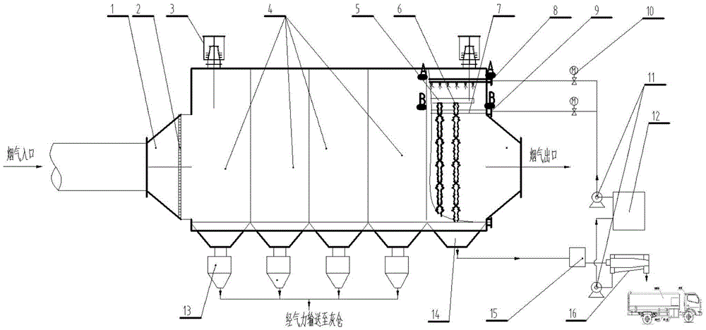
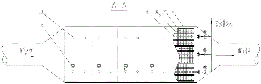
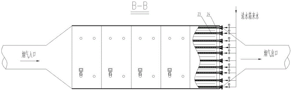
[0030] Combine below figure 1 , figure 2 , image 3 A best specific embodiment of the present invention is given.

[0031] Such as figure 1 , 2 , 3, the high-temperature electric precipitator zone spray flushing coupling continuous water film high-efficiency cleaning device is composed of the dust collector shell, cathode, anode, spray flushing system, water film flushing system, high-voltage power supply, insulator, etc., the overall connection The relationship is as follows:

[0032] One end of the shell is a flue gas inlet, and the opposite end is a flue gas outlet. The bottom of the shell is provided with a plurality of ash hoppers communicating with the inside of the shell, and the inside of the shell is divided into a plurality of In the electric field of the dust collector, and along the direction of the flue gas flow, a spray washing device, a water film washing device, an anode plate and a cathode suspension beam 5 are arranged in the shell of the final electric field fr...


PUM

PropertyMeasurementUnit
Particle sizeaaaaaaaaaa

Abstract

The invention relates to a process and a device for removing ash of a high-temperature electrostatic precipitator by sectional spraying coupling with water film flushing. The device is characterized in that a last-stage electric field ash removing manner is that the sectional spraying and a continuous water film are coupled to enable efficient ash removing, and cathodic and anodic vibrating ash removing systems are saved; a composite anode plate with high surface water film forming property is used as an anode; a clean water tank is used as a water source of a water film flushing system; a main water film flushing tube is firmly welded to a plurality of anodic water distributing tubes to form an independent pipe network; the clean water tank is used as the water source of a spraying flushing system, and a plurality of branch tubes are welded in a fishbone form at two sides of each main spraying flushing tube; water film flushing liquid flows through the surface of the composite anode plate by water outlet holes in the bottom parts of the anodic water distributing tubes so as to completely flush away ash particles deposited on the surface of the anode plate, and then the water film flushing liquid flows into a sewage tank; the liquid in the sewage tank is separated through a horizontal screw centrifuge; the clean liquid is pumped into the clean water tank, and the sludge is recycled; the spraying amount and starting frequency of the spraying flushing pipe network are set based on the principle that the instantaneous smoke humidity variation is controlled to be 0.5 to 2%.

Description

technical field [0001] The invention belongs to the field of air pollutant control, and in particular relates to a process and device for partition spray flushing coupling continuous water film dust removal suitable for high-temperature electrostatic precipitators. Background technique [0002] In view of the severe situation of environmental protection management in my country, the smoke and dust emission concentration standards of active coal-fired power plants must basically meet or approach the emission limit of gas turbine units, that is, the total particle concentration at the chimney inlet is less than 5mg / Nm 3 . For large coal-fired generating units, the flue gas purification technology route after coal combustion generally needs to go through low-nitrogen combustion in the furnace → selective catalytic reduction denitrification → electrostatic dust removal → limestone gypsum wet desulfurization → wet Electrostatic precipitator. Among them, the wet electrostatic pr...

Claims


Application Information

Patent Timeline
IPC IPC(8): B03C3/78
CPCB03C3/78
Inventor 常景彩马春元王鹏崔琳王翔张静
Owner SHANDONG UNIV
Why Eureka
Try Eureka