Ladle furnace (LF) refining steel ladle sealing device and use method thereof

A closed device and ladle technology, which is applied in the field of smelting devices, can solve problems such as short residence time, environmental pollution, and large calcium burning loss, and achieve the effects of avoiding secondary oxidation, protecting the environment, and reducing emissions

Inactive Publication Date: 2016-03-23
高志勇 +1
View PDF4 Cites 0 Cited by
  • Summary
  • Abstract
  • Description
  • Claims
  • Application Information

AI Technical Summary

Problems solved by technology

Therefore, some calcium-rich areas in molten steel will generate low-melting calcium-aluminate (12CaO 7Al 2 o 3 ), while in places where calcium is not enriched (i.e. Al 2 o 3 Inclusion modification is insufficient), not only can not generate liquid 12CaO·7Al 2 o 3 , it is also possible to generate solid calcium and aluminum composite inclusions with high melting point (CaO 2 ·Al 2 o 3 , the melting point is 1750°C), so not only can it not purify the molten steel and solve the blockage of the nozzle, but the nodulation phenomenon will be more serious than that without calcium treatment
[0005] Open ladle feeds silicon-calcium wire, such as Image 6 Shown: The calcium in the calcium-silicon wire fed into the molten steel is turned out to produce bright light. The reason for the bright light is that the calcium fed into the molten steel stays in

Method used


Image

  • Ladle furnace (LF) refining steel ladle sealing device and use method thereof
  • Ladle furnace (LF) refining steel ladle sealing device and use method thereof
  • Ladle furnace (LF) refining steel ladle sealing device and use method thereof

Examples


Embodiment 1

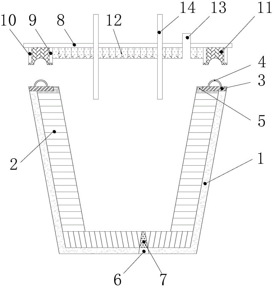
[0045] Embodiment 1: as figure 1 As shown, a kind of LF refining ladle closing device described in the embodiment of the present invention includes a cladding body and a cladding cover;

[0046]The enclosure includes an enclosure 1 and an inner lining layer 2 formed by stacking refractory bricks; the inner lining layer 2 is arranged on the inner bottom and inner side wall of the enclosure; Attached to the air inlet 6 is a porous brick 7 which is of the same height as the bottom lining layer; the argon gas blown into the ladle passes through the hole.

[0047] The first annular steel plate 3 is welded and fixed on the outer edge of the top of cladding 1, and the first annular steel plate 3 extends to the top of the inner liner, and the width of the first annular steel plate 3 is 10-15mm shorter than the refractory brick on the ladle; A plurality of steel bar bars 5 are welded and fixed in the thickness direction of an annular steel plate 3, and the quantity of the steel bar b...

Embodiment 2

[0051] Embodiment 2: the using method of a kind of LF refining ladle sealing device of the present invention, this method comprises:

[0052] Add molten steel into the bag;

[0053] Install an electric hoist next to the waiting station, and fix the ladle cover on the electric hoist;

[0054] When the ladle car advances or retreats into the waiting position, the ladle cover on the electric hoist moves up and down to cover the ladle cover on the ladle; the second and third annular steel plates welded on the ladle cover are just stuck outside the ladle Along the semi-circular tube, the asbestos filling layer on the ladle cover just presses the semi-circular tube on the ladle, so that the molten steel in the ladle can be sealed by improving the ladle and adding the cover;

[0055] The alloy core wire fed by the wire feeding machine is selected and introduced into two wire feeding tubes. The alloy core wire uses silicon-calcium wire and calcium-magnesium wire; by controlling the w...

Embodiment 3

[0083] Embodiment 3: the application of ladle closed wire feeding method and the selection of calcium magnesium wire:

[0084] After the molten steel is refined, it is no problem to feed the silicon-calcium wire to the molten steel to further deoxidize and desulfurize the molten steel, but there are conditions for the denaturation of calcium. When the sulfur in molten steel is 0.010% to 0.015%, there will be CaS is generated; when the sulfur in molten steel is 0.030% to 0.040%, calcium treatment will first generate CaS, which will seriously block the nozzle. From this, we can conclude that the calcified molten steel inside the molten steel forms high-melting-point substances, which are similar to the formation of high-melting-point substances by deoxidizing aluminum. These high-melting point substances must be discharged from the molten steel, otherwise the steel The amount of dissolved oxygen is reduced, but the deoxidized or calcified particles suspended in the molten steel ...


PUM


Abstract

The invention discloses a ladle furnace (LF) refining steel ladle sealing device and a use method thereof. The LF refining steel ladle sealing device comprises a ladle body and a ladle cover. The bottom edge of the ladle cover and the top edge of the ladle body are sealed and buckled. The ladle cover is provided with one or more wire feeding pipes. When the ladle cover and the ladle body are buckled, the bottoms of the wire feeding pipes are located above molten steel inside the ladle body. When the LF refining steel ladle sealing device is used, the ladle cover is sealed on the ladle body through hoisting equipment, alloy core wires penetrate through the wire feeding pipes, and the wire feeding depth is controlled to be 100-200 mm below the interface of the molten steel. The ladle body is sealed through the ladle cover, so that contact burning of strong deoxidizer and oxygen in air on the steel slag interface is avoided, and loss of the strong deoxidizer is reduced. Contact burning of the alloy core wires and the oxygen is reduced, and the situation that calcium compounds in the molten steel cannot be drained and pollutes the molten steel is avoided. Secondary oxidization of the molten steel in the wire feeding process is avoided, dust emission is reduced, and the environment is protected.

Description

technical field [0001] The invention relates to the technical field of smelting devices, in particular to an LF refining ladle closing device and a method for using the same. Background technique [0002] Although the converter slag blocking technology has been continuously improved and matured day by day, it is quite difficult to tap the converter with less slag in actual production, and how to denature the converter slag entering the ladle is extremely important. For the production of aluminum-deoxidized high-quality steel, it is best to control the (FeO+MnO) content in the slag to the minimum at the LF waiting position, so as to avoid the interaction between the oxygen in the slag and the elements of the molten steel, and the formation of oxide inclusions into the molten steel. Especially for aluminum deoxidized molten steel, the generated deoxidized product Al 2 o 3 It is relatively small, so that once the inclusions are involved in the molten steel, it is difficult to...

Claims


Application Information

Patent Timeline
IPC IPC(8): C21C7/00C21C7/06
Inventor 高志勇高志英
Owner 高志勇
Why Eureka
Try Eureka