

Broadband slot antenna with filter character
A technology of slot antenna and filtering characteristics, applied in the field of planar antennas, can solve the problems of difficult to see the slot antenna, lack of filtering characteristics of the antenna, lack of filtering characteristics, etc., and achieve the effect of simple design, low cost and small size
- Summary
- Abstract
- Description
- Claims
- Application Information
AI Technical Summary
Problems solved by technology
Method used
Image

Examples
Embodiment 1
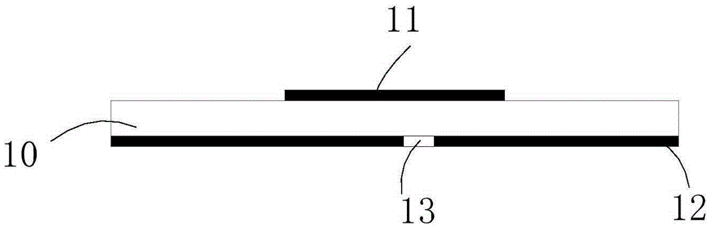
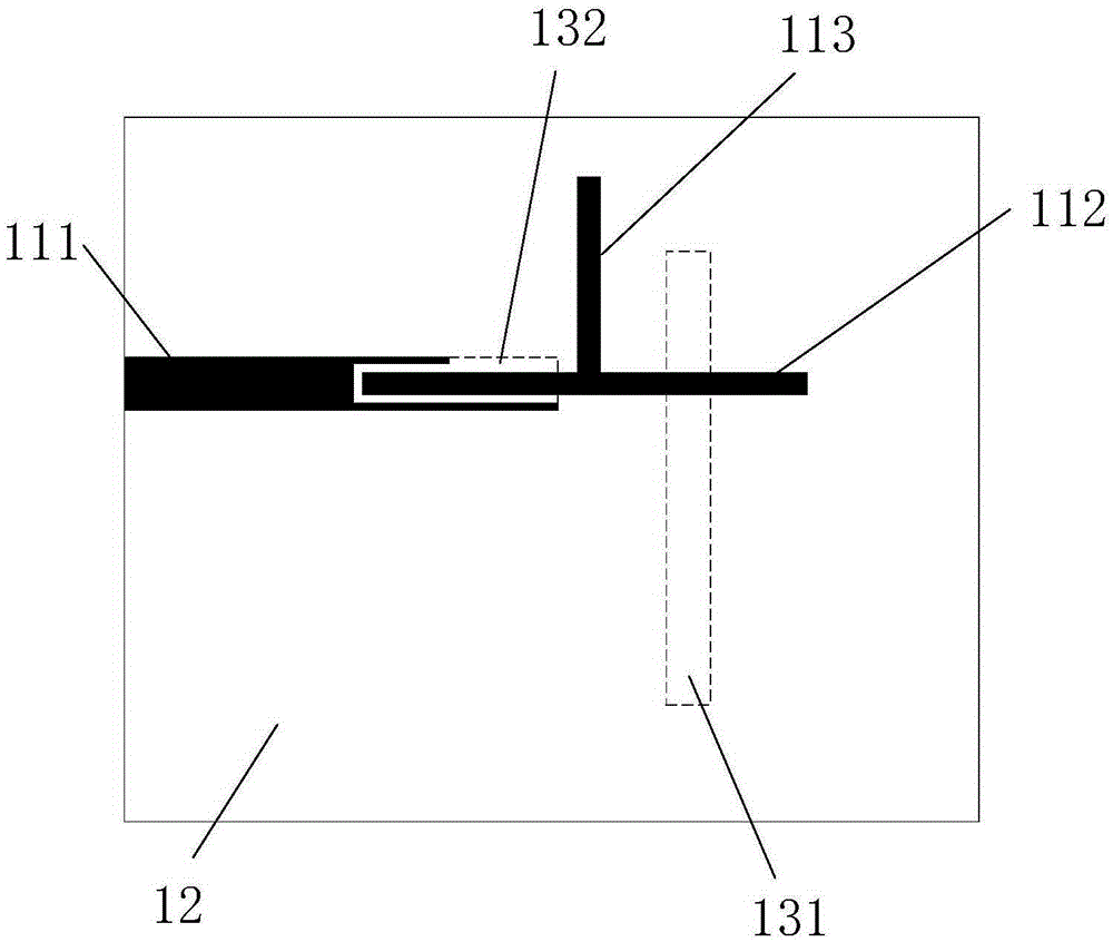
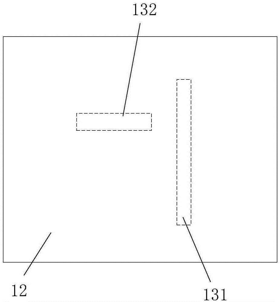
[0034] figure 1 , 2 , 3 are the vertical cross-sectional view, the two-dimensional structural schematic diagram and the bottom schematic diagram of the slot antenna, including the dielectric substrate 10, the microstrip structure 11 formed by the metal foil on the upper surface of the dielectric substrate 10, the ground 12 formed by the metal foil on the lower surface of the substrate 10, and A slot structure 13 formed by digging a groove in the ground 12 . The microstrip structure 11 includes a microstrip feed structure 111 , a first microstrip resonator structure 112 and a second microstrip resonator substructure 113 , and the slot structure 13 includes a first slot structure 131 and a second slot structure 132 . The length of the first microstrip resonator structure 112 is 1 / 2 wavelength, the length of the second microstrip resonator structure 113 is about 1 / 4 wavelength, and the second microstrip resonator structure 113 is placed in the center of the first microstrip reso...
Embodiment 2
[0038] Figure 4 , 5 They are the vertical cross-sectional view and the two-dimensional structure schematic diagram of the slot antenna respectively. On the basis of Embodiment 1, the metal via hole 14 in the dielectric substrate 10 is added, and the third microstrip resonator structure 114 replaces the first embodiment in the embodiment. Two microstrip resonator structures 113 . The length of the third microstrip resonator structure 114 is about 1 / 4 wavelength, and the third microstrip resonator structure 114 is perpendicular to the first microstrip resonator structure 112 . The metal via 14 is placed on an edge of the third microstrip resonator structure 114 away from the first microstrip resonator structure 112 .
[0039] Figure 7It is the |S11| and gain simulation results of the broadband slot antenna with filter characteristics in embodiment 2. The 10dB return loss range of the slot antenna is 4.0GHz to 6.4GHz, and the relative bandwidth has reached 46.2%, which is in...
PUM
 Abstract
Description
Claims
Application Information