Light guide test device

A test device and light guide technology, applied in the field of detectors, can solve problems such as low efficiency and long experiment cycle, and achieve the effect of simple process, high consistency and improved resolution

Inactive Publication Date: 2016-03-30
BEIJING TOP GRADE HEALTHCARE MEDICAL EQUIP CO LTD
View PDF6 Cites 4 Cited by
  • Summary
  • Abstract
  • Description
  • Claims
  • Application Information

AI Technical Summary

Problems solved by technology

[0006] In order to overcome the problems of long experimental cycle and low efficiency of traditional ordinary photomultiplier tube detectors, the present invention provides a light guide testing device

Method used


Image

  • Light guide test device
  • Light guide test device
  • Light guide test device

Examples


Embodiment Construction

[0031] In order to make the technical problems, technical solutions and advantages to be solved by the present invention clearer, the following will describe in detail with reference to the drawings and specific embodiments.

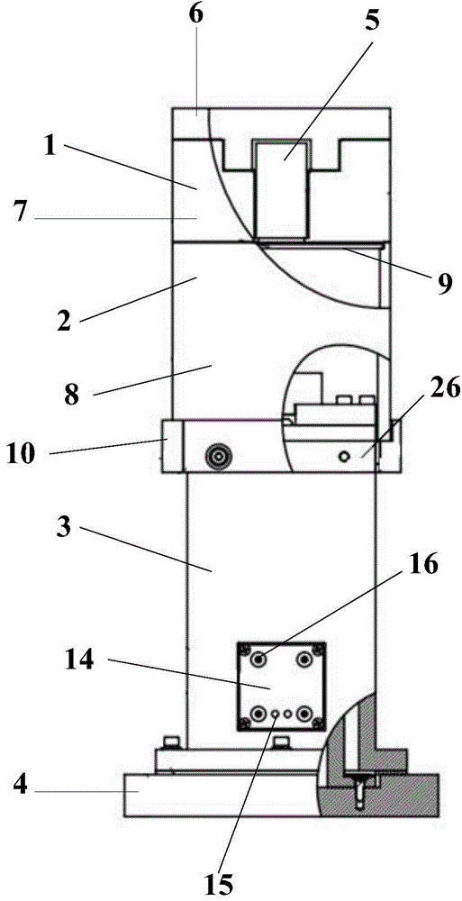
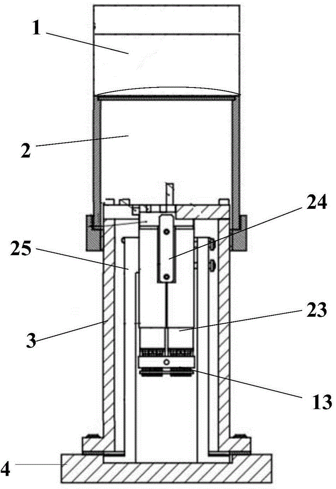
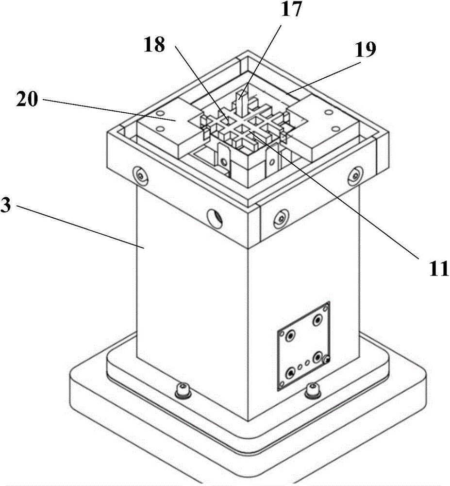
[0032] see figure 1 , the present invention provides a light guide testing device, comprising: a radiation source box 1, a crystal box 2, a photomultiplier tube box 3 and a bottom plate 4 connected sequentially from top to bottom;

[0033] The radioactive source box 1 includes: a radioactive source 5, a radioactive source box cover 6 and a radioactive source box body 7; the radioactive source 5 is placed in the radioactive source box body 7 facing downward; the radioactive source box cover 6 is located at the upper end of the radioactive source box body 7; Further, the radiation source 5 is a γ-ray radiation source; the material of the radiation source box 1 is a shielding material, which can effectively prevent the light emitted by the radiation source ...


PUM


Abstract

The invention provides a light guide test device comprising a radioactive source box, a crystal holder, a photomultiplier tube box and a bottom plate which are connected sequentially from top to bottom. The radioactive source box comprises a radioactive source, a radioactive source box cover and a radioactive source box body. The crystal holder comprises a crystal holder body, a crystal holder cover, a crystal holder fixing plate, a crystal module and a to-be-detected light guide. The crystal holder body is fixed above the to-be-detected light guide through the crystal holder fixing plate. The to-be-detected light guide is fixed above the photomultiplier tube box through a plurality of spring clips. The photomultiplier tube box is fixed on the bottom plate. The photomultiplier tube box is internally equipped with a plurality of photomultiplier tubes. The photomultiplier tube box is externally equipped with a connector board which is provided with high-voltage power input ends and data output ends. The high-voltage power input ends are connected with the power input ends of the photomultiplier tubes. The signal output ends of the photomultiplier tubes are connected with a detector test platform through the data output ends.

Description

technical field [0001] The invention relates to the technical field of detectors, in particular to a light guide testing device. Background technique [0002] Positron Emission Tomography (PET, Positron Emission Tomography) is a relatively advanced clinical examination imaging technology that applies computed tomography technology to the field of nuclear medicine after X-ray tomography and magnetic resonance imaging technology. The new imaging technology of molecular metabolism, receptors and neurotransmitter activities has been widely used in the diagnosis and differential diagnosis of various diseases, disease judgment, curative effect evaluation, organ function research and new drug development, etc. [0003] A PET scanner is composed of a detector, front-end electronics, an examination bed, a computer and other auxiliary parts, and the detector is the core component of PET and the "eye" of PET. The technical indicators of a PET scanner, such as position resolution, time...

Claims


Application Information

Patent Timeline
Patent Type & Authority Applications(China)
IPC IPC(8): G01M11/00
Inventor 严李李刘小平李景涛牛绍龙宋山山
Owner BEIJING TOP GRADE HEALTHCARE MEDICAL EQUIP CO LTD
Why Eureka
Try Eureka