Boiler power generation system utilizing rubbish gasification and incineration synthesis gas

A technology for boiler power generation and synthesis gas, which is used in steam boilers, steam generation, and liquid degassing. The effect of improving heat exchange efficiency and preventing secondary pollution

Active Publication Date: 2016-04-06
CHONGQING UNIVERSITY OF SCIENCE AND TECHNOLOGY
View PDF9 Cites 3 Cited by
  • Summary
  • Abstract
  • Description
  • Claims
  • Application Information

AI Technical Summary

Problems solved by technology

At the same time, the fly ash content in the flue gas after incineration is high, the boiler ash is heavy, and the ash cleaning maintenance period is short
[0007] 2. With the increasing amount of garbage generated and piled up like mountains, the amount of garbage treatment must be effectively increased in order to meet market demand
[0010] Existing gasification incinerators, such as the following two invention patents: Multi-column segmented drive compound domestic waste incinerator (ZL200710092508.9) and two-stage waste incinerator (ZL201010268376.2) Unsolved problems: heat treatment of waste The mode is relatively backward, just drying-burning-burning, the process of solid combustion releasing heat; the thermochemical reaction in the furnace is dominated by oxidation reaction, supplemented by reduction reaction, which is easy to produce secondary pollutants; when garbage is burned in the furnace, the peroxygen coefficient Large, large amount of primary air and secondary air supply, high dust content in flue gas, great impact on heat energy recovery system and flue gas treatment system, easy to accumulate dust, large amount of flue gas, reducing heat conversion efficiency; Without a separate gasification furnace and ember furnace, waste can only be processed in batches, and large-scale continuous gasification and incineration of waste cannot be realized, and the amount of waste treated is small

Method used


Image

  • Boiler power generation system utilizing rubbish gasification and incineration synthesis gas
  • Boiler power generation system utilizing rubbish gasification and incineration synthesis gas
  • Boiler power generation system utilizing rubbish gasification and incineration synthesis gas

Examples


Embodiment Construction

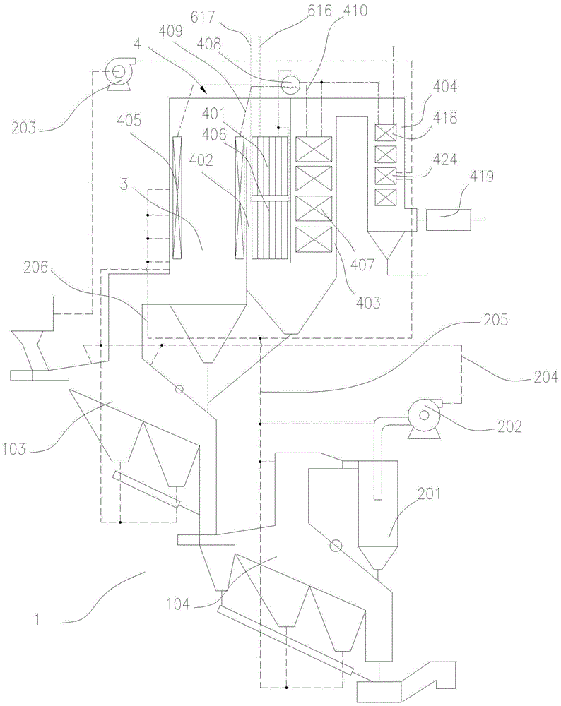
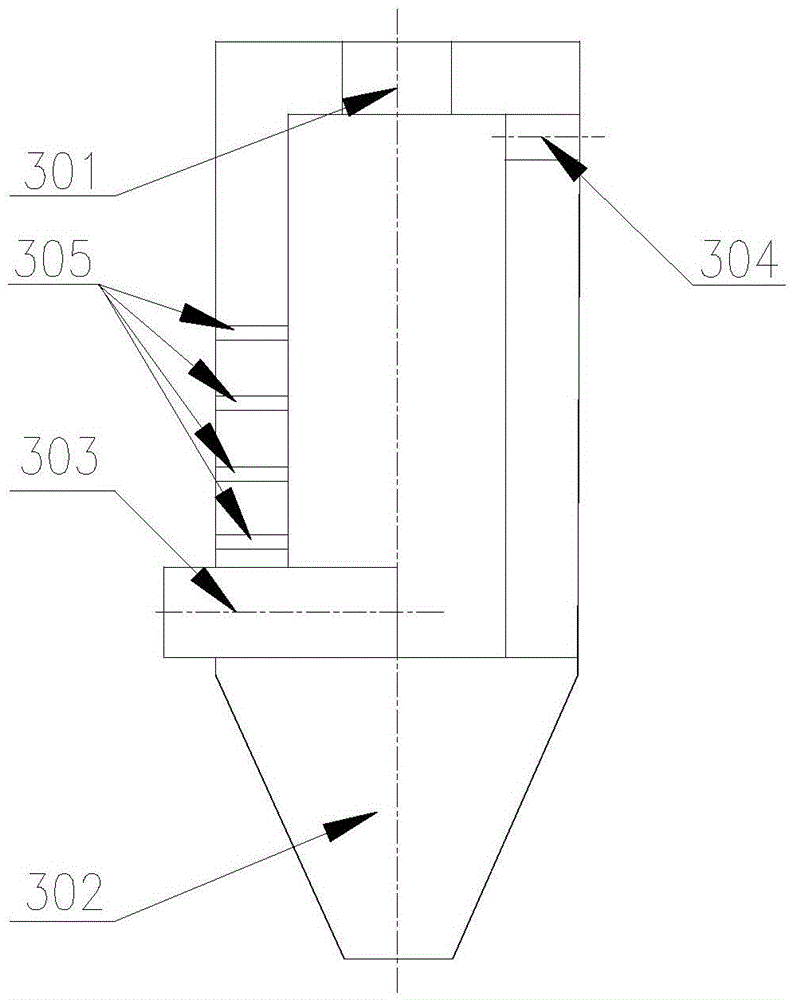
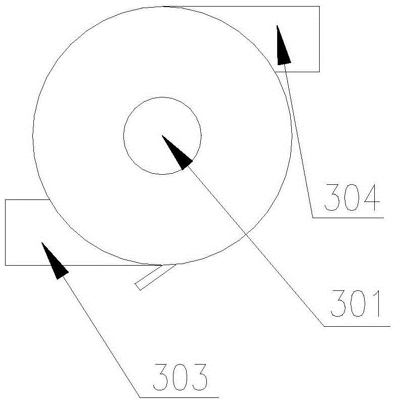
[0045] see Figure 1 to Figure 7 , which is a preferred embodiment of a boiler power generation system using waste gasification and incineration of syngas.

[0046] see Figure 4 The power generation system includes a steam turbine and a generator 613 power-connected with the steam turbine. The steam turbine includes a high-pressure cylinder 601, a medium-pressure cylinder 602, and a low-pressure cylinder 603. A first-stage water vapor is arranged between the high-pressure cylinder 601 and the medium-pressure cylinder 602. Separator 604, first-stage high-pressure steam heater 605, the input end of the first-stage water-steam separator 604 is connected to the output end of the high-pressure cylinder 601 through a pipeline, and the steam output end of the first-stage water-steam separator 604 is connected to the first-stage water-steam separator 604. The heating input end of the first-stage high-pressure steam heater 605 is connected through a pipeline, and the heating output e...


PUM


Abstract

The invention discloses a boiler power generation system utilizing rubbish gasification and incineration synthesis gas. The boiler power generation system is small in heat conversion efficiency loss and higher in heat recovery efficiency. The boiler power generation system comprises a steam turbine, a generator, a high-pressure steam input pipe and a medium-pressure steam input pipe. The steam turbine comprises a high-pressure steam cylinder, a medium-pressure steam cylinder and a low-pressure steam cylinder. A first-stage water-steam separator and a first-stage high-pressure steam-steam heater are connected between the high-pressure steam cylinder and the medium-pressure steam cylinder. A second-stage water-steam separator and a second-stage high-pressure steam-steam heater are connected between the medium-pressure steam cylinder and the low-pressure steam cylinder. The steam output end of the low-pressure steam cylinder is connected with a condenser, a water pump, a low-pressure steam-water heater, a deaerator, a booster water pump and a high-pressure steam-water heater in sequence through a pipeline. The high-pressure steam input pipe is connected with the high-pressure steam cylinder and is connected with the deaerator through the heating end of the first-stage high-pressure steam-steam heater, the heating end of the high-pressure steam-water heater, the heating end of the second-stage high-pressure steam-steam heater and the heating end of the low-pressure steam-water heater.

Description

technical field [0001] The invention belongs to the technical field of solid waste incineration treatment, and in particular relates to a boiler power generation system using waste gasification to incinerate synthesis gas. Background technique [0002] The existing waste treatment technologies mainly include incineration, sanitary landfill, composting, and waste recycling. Among the conventional waste treatment technologies, incineration has the advantages of obvious reduction effect, complete harmlessness, small land occupation, utilization of waste heat energy, and less secondary pollution, which meets the strategic requirements of my country's sustainable development. However, with the continuous improvement of environmental protection requirements at home and abroad, how to strengthen the control of secondary pollution is particularly important. Therefore, waste pyrolysis and gasification incineration technology is gradually pushed to the road of industrial application,...

Claims


Application Information

Patent Timeline
IPC IPC(8): F01K11/02F22B31/08F22D1/50
CPCF01K11/02F22B31/08F22D1/50
Inventor 严欣平肖大志周雄林顺洪李长江丁又青徐明季炫宇田野
Owner CHONGQING UNIVERSITY OF SCIENCE AND TECHNOLOGY
Why Eureka
Try Eureka