
Braking energy recovery system for electric vehicle

A braking energy recovery, electric vehicle technology, applied in the field of electronics, can solve the problems of battery output current ripple, excessive charging current, battery damage, etc., to reduce current ripple, prevent current runaway, and improve reliability. Effect

Active Publication Date: 2016-04-13
CHONGQING UNIV OF POSTS & TELECOMM
View PDF7 Cites 30 Cited by
  • Summary
  • Abstract
  • Description
  • Claims
  • Application Information

AI Technical Summary

Problems solved by technology

[0003] Traditional high-power devices used for energy recovery adopt single-phase operation mode, which has certain restrictions on the improvement of converter capacity, efficiency and output power quality, and has the characteristics of large volume and large ripple current. MCU applications also have certain limitations
[0004] The battery charging methods in the electric energy storage system generally include constant voltage and current limiting, constant current and voltage limiting, constant current first and then constant voltage, etc. No matter which mode is selected, the charging current may be too large or too Small problem, if the current ripple is too large, it will be harmful to some current ripple sensitive batteries
When the battery is discharged, the converter works in Boost mode, and the charging and discharging effect of the inductance in the circuit will inevitably cause the output current ripple of the battery

Method used


Image

  • Braking energy recovery system for electric vehicle
  • Braking energy recovery system for electric vehicle
  • Braking energy recovery system for electric vehicle

Examples


Embodiment Construction

[0030] The preferred embodiments of the present invention will be described in detail below with reference to the accompanying drawings.

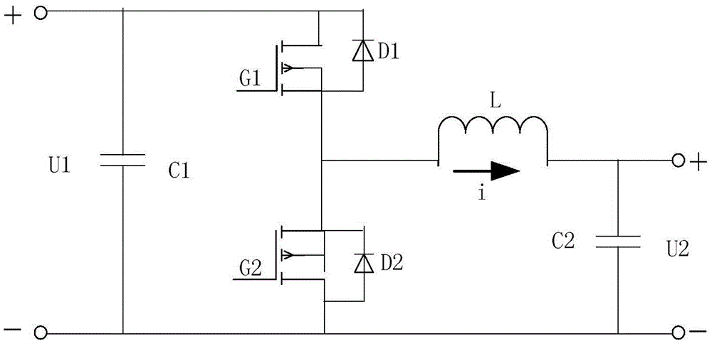
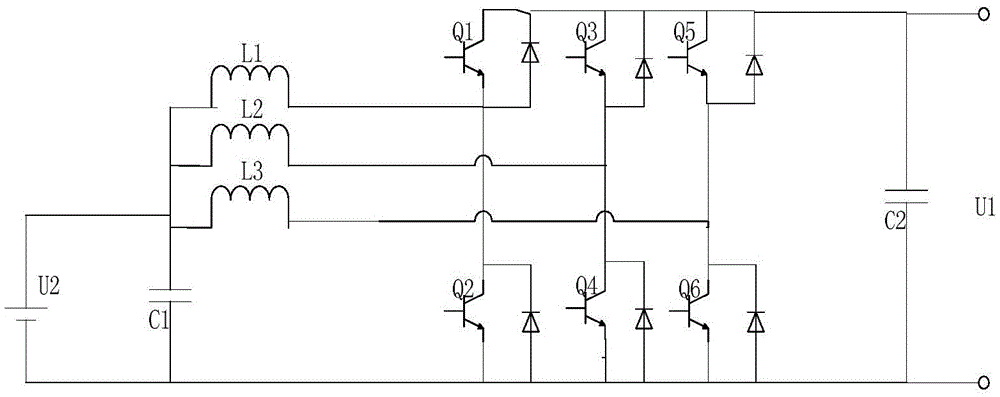
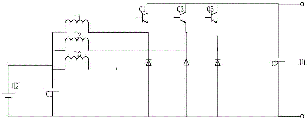
[0031] The principle of the present invention is to obtain a three-phase interleaved bidirectional half-bridge circuit by paralleling the bidirectional half-bridge DC / DC converters, and realize the switching of the DC / DC circuit in the BUCK / BOOST mode by controlling the on-off of the switching tube. In order to achieve the purpose of providing electric energy for the DC motor and recovering the energy of the DC motor under the braking state; and the energy recovery system of the invention can control the on-off of the relay through the I / O port of the digital chip to select different power The required gear position finally achieves the purpose of recovering braking energy for motors with different output powers by adjusting the gear position.

[0032] figure 1 It is a typical bidirectional half-bridge type DC / DC circuit diagram. Compared ...


PUM


Abstract

The invention relates to a braking energy recovery system for an electric vehicle, comprising a three-phase staggered two-way half-bridge circuit, a gear selection circuit, a sampling hold circuit, a digital chip, a voltage sampling circuit, a current sampling circuit and a driving circuit which are sequentially connected. Two-way half-bridge DC / DC converters are connected in parallel, the three-phase staggered two-way half-bridge circuit serves as a main circuit topology of the system, high and low levels are output through an I / O port to control the switching-on / off of relays so as to select different power requirement gears, and finally, the purpose of recovering the braking energy of motors with different output power is realized. According to the invention, the reliability of the device is improved, current ripples are reduced, and the volume of inductors and the capacity of capacitors are reduced, so that the device is easier to realize; the system can be used for multiple DC motors with different output power requirements; the system can effectively prevent current from being out of control under fault conditions so as to quickly finish overcurrent protection; and in addition, a three-phase staggered DC / DC converter system and an active inverter system are consistent in structure, thereby being favorable for realizing a modular structure of an electric vehicle system.

Description

technical field [0001] The invention belongs to the field of electronic technology, and relates to a braking energy recovery system of an electric vehicle. Background technique [0002] As the government and society pay more and more attention to environmental pollution and energy issues, energy conservation and environmental protection have become one of the main goals of the development of the automobile industry. The development of electric vehicle technology has entered an important stage, and regenerative braking technology, as one of the key technologies for energy saving and environmental protection, has many problems to be solved urgently. During the braking process of the car, a large amount of kinetic energy is converted into heat energy and dissipated through friction, which leads to premature wear of the car brake system and increases the cost of using the car. Energy recovery using regenerative braking is one of the energy-saving advantages of electric vehicles...

Claims


Application Information

Patent Timeline
IPC IPC(8): B60L7/12B60L7/16
CPCB60L7/12B60L7/16B60L2210/10B60L2220/20
Inventor 黄智宇杨焘罗洪平冯辉宗陈波杜尚川
Owner CHONGQING UNIV OF POSTS & TELECOMM
Learn More