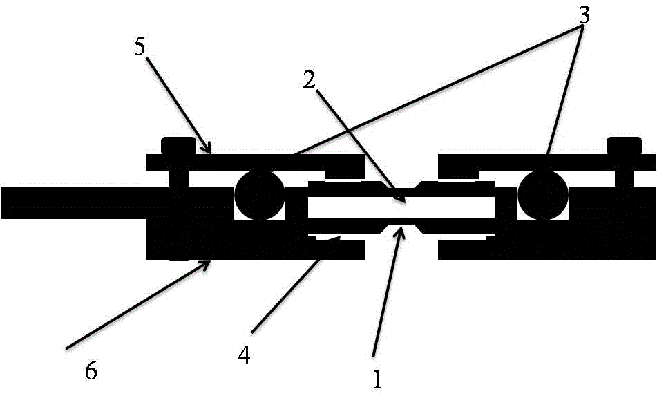
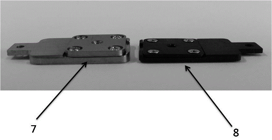
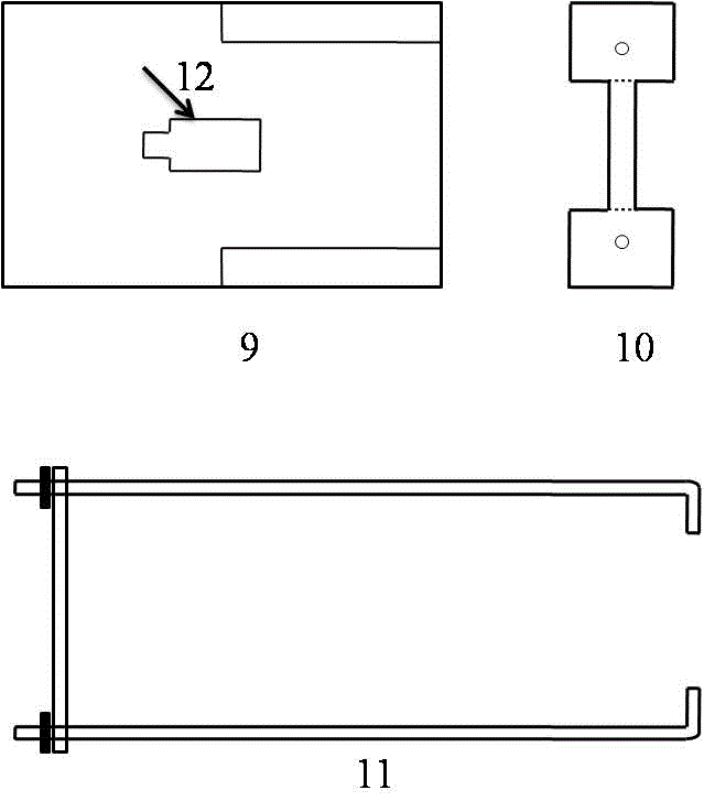
Ultrathin in-situ liquid sample room for transmission electron microscope and auxiliary installation device and installation method for ultrathin in-situ liquid sample room

An electron microscope, liquid sample technology, applied in circuits, discharge tubes, electrical components, etc., can solve problems such as difficulty in grasping the amount of resin, reduced sealing, and sample contamination.

Active Publication Date: 2016-04-13
南通励思仪电子科技有限公司
View PDF5 Cites 18 Cited by
  • Summary
  • Abstract
  • Description
  • Claims
  • Application Information

AI Technical Summary

Problems solved by technology

[0005] As mentioned above, the liquid sample chamber developed by M.J.Williamson et al. is mainly assembled by bonding silicon nitride windows with vacuum resin. Although it has achieved great success, it also has obvious shortcomings: 1. The sample chamber is suitable for one-time use. It is difficult to effectively recycle; 2. When using resin to seal, the amount of resin is not easy to grasp. Too much resin is easy to enter the liquid layer and cause sample contamination. Too little resin is used and the sealing performance is reduced.
In addition to enhancing the function of the in-situ liquid TEM device, this method also has some problems: if the film window breaks during the TEM experiment, there may be more liquid leaking into the electron microscope due to the pipeline delivering liquid to the liquid chamber. Vacuum system causing adverse effects

Method used


Image

  • Ultrathin in-situ liquid sample room for transmission electron microscope and auxiliary installation device and installation method for ultrathin in-situ liquid sample room
  • Ultrathin in-situ liquid sample room for transmission electron microscope and auxiliary installation device and installation method for ultrathin in-situ liquid sample room
  • Ultrathin in-situ liquid sample room for transmission electron microscope and auxiliary installation device and installation method for ultrathin in-situ liquid sample room

Examples


Embodiment 1

[0038] Use 502 glue to glue the silicon nitride window substrate on the liquid chamber base and cover sheet, and add 0.5g / L of 10nm nano Ag solution ~1ul to the vicinity of the silicon nitride window of the in-situ liquid chamber, follow the above steps After the encapsulation in the single-ring sealed ultra-thin in-situ liquid sample chamber is completed, it is pre-evacuated for leak detection and placed under an optical microscope to observe the results as follows Figure 7 As shown, the silicon nitride window is intact and undamaged. And put the sample under the transmission electron microscope to obtain Picture 8 The photo of the nano Ag particles shown in the liquid.

Embodiment 2

[0040] Use 502 glue to glue the silicon nitride window substrate on the liquid chamber base and cover sheet respectively, and drop 0.5g / L of 10nm nano Ag solution ~1ul onto the silicon nitride window of the in-situ liquid box, follow the above steps After encapsulation in a single-ring sealed ultra-thin in-situ liquid sample chamber is completed, it is pre-evacuated for leak detection and placed under an optical microscope to obtain Figure 7 As shown, the silicon nitride window is intact and undamaged. And put the sample under the transmission electron microscope to select an appropriate area to observe the results as Picture 9 As shown, in addition to the nanoparticles, a large number of nanobubbles are also observed in the liquid.

Embodiment 3

[0042] Design and process the liquid chamber with multiple rubber rings in accordance with the size of the auxiliary installation device, and use the auxiliary installation device to install, change the part where the sealant is applied to the seal ring, and add 0.5g / L 10nm nano Ag solution ~1ul dropwise to the original On the silicon nitride window of the liquid box, follow the above steps to encapsulate the in-situ liquid sample chamber. After pre-vacuum leak detection and observation and inspection under an optical microscope, install it on the TEM sample rod (such as Picture 10 Shown). And put the sample into the transmission electron microscope to observe, select the sample area to take a photo at the appropriate magnification, the result is as follows Picture 11 As shown, not only the presence of nanoparticles in the liquid is observed, but also a few particles on the photo are blurry, showing the dynamic information of the particles moving in the liquid in real time. E...


PUM


Abstract

The invention aims at disclosing an ultrathin in-situ liquid sample room for a transmission electron microscope and an auxiliary installation device and installation method for the ultrathin in-situ liquid sample room. By design of a single rubber ring-sealed sample room and a synergistic effect of the auxiliary installation device, the thickness and the width of the in-situ liquid sample room are reduced; assembly is relatively safe and reliable; and relatively effective utilization of a small sample space in the transmission electron microscope and achievement of relatively multiple functions carried on the in-situ liquid sample room are facilitated.

Description

Technical field [0001] The invention relates to an ultra-thin in-situ liquid sample chamber for a transmission electron microscope, an auxiliary installation device and an installation method thereof. Specifically, it relates to an ultra-thin in-situ liquid sample chamber in which a single rubber ring (O-ring) replaces multiple rubber rings, and an auxiliary installation device is used to assist assembly instead of rotating installation. Compared with the current in-situ liquid sample chamber, the new installation method is more convenient to make the in-situ liquid sample chamber thinner and narrower in width, which is beneficial to realize the in-situ liquid sample chamber in the limited vacuum chamber of the transmission electron microscope. The multi-functional carrying, promotes the development of liquid in-situ electron microscope towards multi-functional and highly integrated. Background technique [0002] Transmission electron microscope (transmission electron microscope...

Claims


Application Information

Patent Timeline
Patent Type & Authority Applications(China)
IPC IPC(8): H01J37/20H01J37/26
CPCH01J37/20H01J37/261H01J37/26H01J2237/2003H01J2237/2608
Inventor 陈新李唱曹红亮
Owner 南通励思仪电子科技有限公司
Why Eureka
Try Eureka