

Technology and device for separating and melting sulfur
A technology for melting sulfur and equipment, which is applied in the preparation/purification of sulfur, sulfur compounds, inorganic chemistry, etc., can solve the problems of affecting the service cycle of changing and removing posts, increasing the cost of melting sulfur, and low desulfurization efficiency of the desulfurization system. Large amount of circulating secondary salts, lower fertilizer production costs, and beneficial effects on stable operation
- Summary
- Abstract
- Description
- Claims
- Application Information
AI Technical Summary
Problems solved by technology
Method used
Image

Examples
Embodiment Construction
[0023] The present invention will be further described below through embodiment.
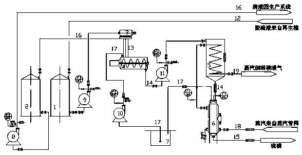
[0024] A device for separating and melting sulfur, comprising a rich liquid tank 1, a desulfurization liquid tank 2, a desulfurization filter press 3, a spiral stirring tank 4, a high level tank 5, a sulfur melting kettle 6, a return liquid precipitation cooling pool 7, a desulfurization pump 8, a dilute Foam pump 9, molten sulfur return pump 10 and dense foam pump 11, rich liquid tank 1 is connected with desulfurization filter press 3 through thin foam pump 9, sulfur paste 13 output by desulfurization filter press 3 enters spiral stirring tank 4, spiral The mixed solution 14 of the stirring tank 4 enters the head tank 5 through the dense foam pump 11, enters the sulfur melting tank 6 to separate the sulfur 15; the molten sulfur liquid 17 of the sulfur melting tank 6 enters the return liquid precipitation cooling pool 7, and passes through the sulfur melting return liquid pump 10 into the spiral...
PUM
 Abstract
Description
Claims
Application Information