
Thermal activation delayed fluorescent material and organic electroluminescent device

A technology of thermally activated delay and fluorescent materials, which is applied in luminescent materials, electrical solid devices, organic chemistry, etc., can solve the problems of low efficiency of the luminescent layer, achieve high radiative transition rate, small dihedral angle, improve efficiency and stability Effect

Active Publication Date: 2016-04-20
KUNSHAN GO VISIONOX OPTO ELECTRONICS CO LTD +1
View PDF4 Cites 69 Cited by
  • Summary
  • Abstract
  • Description
  • Claims
  • Application Information

AI Technical Summary

Problems solved by technology

[0005] For this reason, the present invention aims at the problem of the low efficiency of the light-emitting layer of the existing OLED, and provides a thermally activated delayed fluorescent material whose singlet-triplet energy gap (ΔE ST ) is very small, the triplet excitons can be transformed into singlet excitons to emit light through reverse intersystem jumping (RIST), which can improve the efficiency and stability of OLED devices

Method used


Image

  • Thermal activation delayed fluorescent material and organic electroluminescent device
  • Thermal activation delayed fluorescent material and organic electroluminescent device
  • Thermal activation delayed fluorescent material and organic electroluminescent device

Examples


Embodiment 1

[0068] Synthetic method of the structural compound shown in formula (1-1): under nitrogen range, 3,6-dibromo-9-fluorenone (5mmol), phenoxazine (18mmol), Pd 2 (dba) 3 (0.8mmol), NaOtBu (30mmol) and tBu3P·HBF4 (0.8mmol) were put into 100mL toluene and stirred at 105°C overnight. The reaction was quenched by adding 10 mL of cold water to the mixture. After the mixture was cooled to room temperature, it was vacuum filtered and then purified by column chromatography to obtain the product with the structure shown in formula (1-1). The product was dried in vacuum, yield: 80%.

[0069] The molecular weight obtained by mass spectrometry: 542.58.

[0070] The relative molecular mass percentages of each element obtained by elemental analysis: C: 81.90%; H: 4.09%; N: 5.16%; O: 8.85%.

Embodiment 2

[0072] Synthetic method of the structural compound shown in formula (1-2): the reactant phenoxazine is replaced by phenothiazine, through the same synthetic method as in Example 1, the structural compound shown in formula (1-2) is obtained, and the yield is 91% .

[0073] The molecular weight obtained by mass spectrometry: 574.71.

[0074] The relative molecular mass percentages of each element obtained by elemental analysis: C: 77.32%; H: 3.86%; N: 4.87%; O: 2.78%; S: 11.16%.

Embodiment 3

[0076] Synthesis method of the compound with the structure shown in formula (1-3): the reactant phenoxazine is replaced by 9,9-dimethylacridine, and the structure shown in formula (1-3) is obtained through the same synthesis method as in Example 1 Compound, yield 87%.

[0077] The molecular weight obtained by mass spectrometry: 594.74.

[0078] The relative molecular mass percentages of each element obtained by elemental analysis: C: 86.84%; H: 5.76%; N: 4.71%; O: 2.69%.


PUM


Abstract

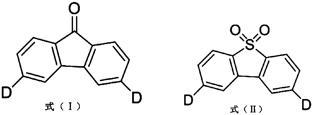
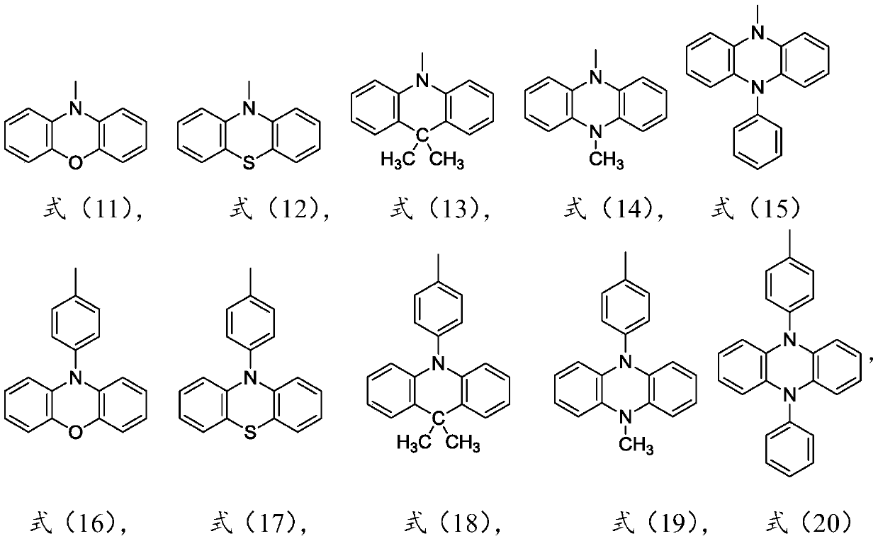
The invention relates to a thermal activation delayed fluorescent material with a general formula of the structure shown as the formula (I) or the formula (II). D is one of phenoxazinyl, phenothizainyl, 9,9-dimethyl acridine, 9-methyl phenazinyl, 9-phenyl phenazinyl, 4-phenoxazinyl-1-phenyl, 4-phenothizainyl-1-phenyl, 4-(9,9-dimethyl)acridinyl-1-phenyl, 4-(9-methyl)-phenazinyl-1-phenyl, 4-(9-phenyl)phenazinyl-1-phenyl and 3,5-bis-carbazolyl-1-phenyl. The invention further relates to an organic electroluminescent device which comprises a light-emitting layer, and luminescent dye of the light-emitting layer is the thermal activation delayed fluorescent material. The singlet state-triplet state energy gap (delta EST) of the thermal activation delayed fluorescent material is very small, triplet state excitors can be converted into singlet state excitors through inverse intersystem crossing (RIST) to emit light, and the efficiency and stability of an OLED device can be improved. The formula is shown in the description.

Description

technical field [0001] The invention relates to the field of organic electroluminescent devices, in particular to a thermally activated delayed fluorescent material that can be used in a light-emitting layer and an organic electroluminescent device with the thermally activated delayed fluorescent material. Background technique [0002] Organic Light Emitting Diode (OLED) is a current-driven light-emitting device that uses organic materials as active materials, specifically refers to organic semiconductor materials and organic light-emitting materials that are driven by an electric field to cause light emission through carrier injection and recombination Technology. Unlike inorganic materials, organic materials have the characteristics of low synthesis cost, adjustable function, flexibility, and good film-forming properties. Moreover, devices based on organic materials are generally simple in fabrication process, easy to be prepared in a large area, and are environmentally f...

Claims


Application Information

Patent Timeline
IPC IPC(8): C07D265/38C07D279/22C07D219/02C07D241/46C07D413/14C07D209/86C07D417/14C07D409/14C09K11/06C09B19/00C09B21/00C09B15/00C09B17/02C09B57/00H01L51/54
CPCC09K11/06C07D209/86C07D219/02C07D241/46C07D265/38C07D279/22C07D409/14C07D413/14C07D417/14C09B15/00C09B17/02C09B19/00C09B21/00C09B57/00C09K2211/1029C09K2211/1011C09K2211/1007C09K2211/1033C09K2211/1037C09K2211/1044C09K2211/1092H10K85/615H10K85/657H10K85/6576H10K85/6572
Inventor 段炼张云阁刘嵩赵菲
Owner KUNSHAN GO VISIONOX OPTO ELECTRONICS CO LTD
Learn More