Gas catalytic flameless heating voc treatment system for paint film drying chamber

A gas catalysis and treatment system technology, applied in drying, drying machines, heating devices, etc., can solve the problems of large consumption of consumables, high operating costs, and heavy workload of activated carbon, achieving high efficiency and thorough exhaust gas treatment Effect

Inactive Publication Date: 2017-12-26
周海波
View PDF9 Cites 0 Cited by
  • Summary
  • Abstract
  • Description
  • Claims
  • Application Information

AI Technical Summary

Problems solved by technology

[0003] The technical problem to be solved by the present invention is to provide a gas-fired catalytic flameless heating VOC treatment system in the paint film drying chamber to solve the existing problems of incomplete waste gas treatment, often more active carbon, and a large amount of consumables. , The disadvantage of high operating costs

Method used


Image

  • Gas catalytic flameless heating voc treatment system for paint film drying chamber
  • Gas catalytic flameless heating voc treatment system for paint film drying chamber

Examples


Embodiment 1

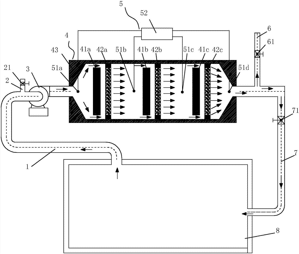
[0050] A gas catalytic flameless heating VOC treatment system in a paint film drying chamber (see figure 1 ), including exhaust fan 3, gas catalytic flameless infrared heating catalytic processor 4, VOC online detection system 5, return air duct 7, of which:

[0051]The air inlet of described exhaust fan 3 is connected with the waste gas outlet of paint film drying chamber 8 by exhaust pipe 1, and the entrance of exhaust fan 3 is equipped with fresh air inlet pipe 2, and fresh air inlet pipe 2 is installed on this fresh air inlet pipe 2. Gas regulating valve 21; the air outlet of the exhaust fan 3 is connected to the inlet of the gas catalytic flameless infrared heating catalytic processor 4 through the air pipe, and the outlet of the gas catalytic flameless infrared heating catalytic processor 4 is connected to the paint film drying through the return air pipe 7 The purification gas recovery port of chamber 8 is connected, and the return air pipe 7 is also provided with a pur...

Embodiment 2

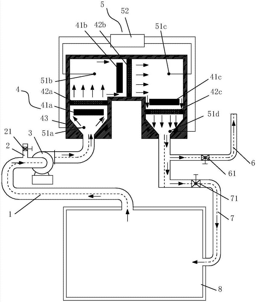
[0058] A gas-fired catalytic flameless heating VOC treatment system in a paint film drying chamber, the basic structure of which is the same as that of Embodiment 1, including an exhaust fan 3, a gas-fired catalytic flameless infrared heating catalytic processor 4, a VOC online detection system 5, and a return air Pipe 7, the difference is that: the three sets of heating catalytic combustion devices of the gas catalytic flameless infrared heating catalytic processor 4 are arranged in a U shape (see figure 2 ).

[0059] Instructions for use of the gas catalytic flameless heating VOC treatment system in the paint film drying chamber:

[0060] In principle, the temperature of the exhaust gas discharged from the top of the paint film drying chamber can reach above 145 degrees, and it can directly enter the first set of heating catalytic combustion device of the gas catalytic flameless infrared heating catalytic processor for treatment without preheating, due to catalytic heat sto...


PUM


Abstract

A gas catalytic flameless heating VOC treatment system for a paint film drying chamber, which relates to a waste gas treatment system for a paint film drying chamber, including an exhaust fan, a gas catalytic flameless infrared heating catalytic processor, a VOC online detection system, and a return air duct , the exhaust fan is connected to the paint film drying chamber through the exhaust pipe, and is also connected to the gas catalytic flameless infrared heating catalytic processor through the gas pipe; the processor includes a shell, a gas catalytic flameless infrared radiation heater and a catalytic heat storage It is a heating and catalytic combustion device composed of a device, which is connected to the paint film drying chamber through the return air pipe, and is also connected to the VOC online detection system. The invention can fully burn the waste gas through the high-efficiency heating of the gas-fired catalytic flameless infrared radiation heater and the heat storage and catalysis of the catalytic heat accumulator. It is characterized by less usage, low operating cost, reduced equipment investment and equipment footprint, and is easy to popularize and use.

Description

technical field [0001] The invention relates to a waste gas treatment system of a paint film drying chamber, in particular to a gas catalytic flameless heating VOC treatment system of a paint film drying chamber. Background technique [0002] With the rapid development of society, the demand for passenger cars such as passenger cars and cars is increasing. In the production process of passenger cars and cars, more and more attention is paid to the quality of surface coating, and the drying of paint film is one of the important steps of surface coating. During the drying process of the paint film, a large amount of exhaust gas will be generated, which will cause air pollution when discharged into the atmosphere. Therefore, existing manufacturers generally use dry treatment systems or wet treatment systems to treat waste gas. Among them, the dry treatment system uses activated carbon adsorption devices to remove harmful gases in the exhaust gas, and then reduces the concentr...

Claims


Application Information

Patent Timeline
Patent Type & Authority Patents(China)
IPC IPC(8): F23G7/07F26B23/02
CPCF23G7/07F26B23/024
Inventor 周海波
Owner 周海波
Why Eureka
Try Eureka