Device and method for controlling motion mode of resonant metal nanoparticles

A technology of metal nanoparticles and movement methods, which is applied in the fields of optical tweezers, optical capture and optical micro-manipulation, and can solve problems such as the insurmountable strong scattering force and thermal effect, and the destruction of control stability.

Active Publication Date: 2016-04-20
SOUTHEAST UNIV
View PDF2 Cites 7 Cited by
  • Summary
  • Abstract
  • Description
  • Claims
  • Application Information

AI Technical Summary

Problems solved by technology

[0005] Purpose of the invention: The present invention proposes a device and method for manipulating metal nanoparticles that can work under extreme conditions, and is used to solve the problem that the existing optical tweezers technology cannot overcome the extremely strong force produced by the metal nanoparticles in the resonance state. The scattering force and thermal effect are difficult to control stability, and can control the movement of target particles stably and effectively

Method used


Image

  • Device and method for controlling motion mode of resonant metal nanoparticles
  • Device and method for controlling motion mode of resonant metal nanoparticles
  • Device and method for controlling motion mode of resonant metal nanoparticles

Examples


Embodiment Construction

[0038] The present invention will be further described below in conjunction with the accompanying drawings.

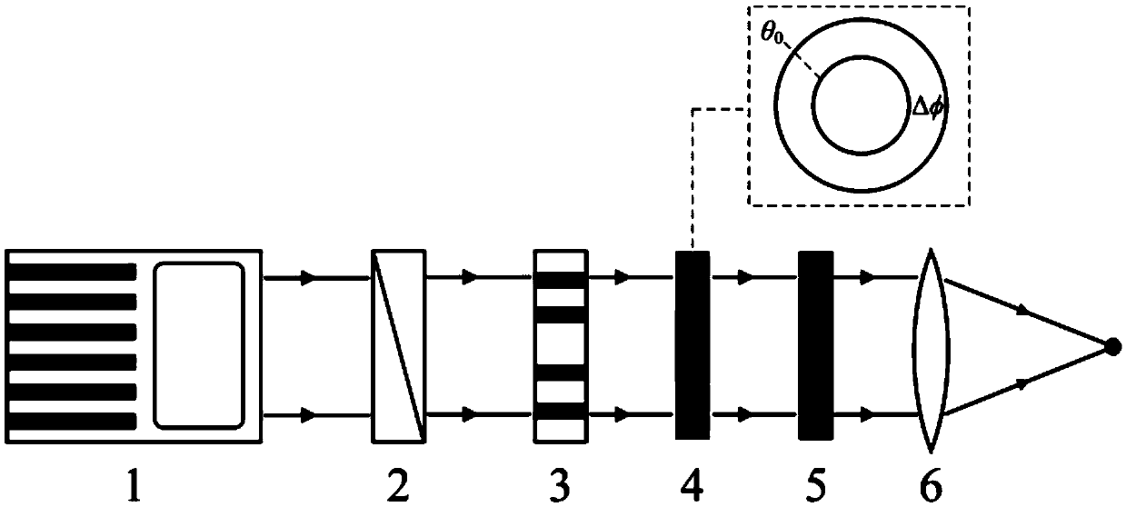
[0039] Such as figure 1 As shown, a device that can control the movement mode of resonant metal nanoparticles can be divided into six parts: laser 1, polarization converter 2, spatial light modulator 3, diffractive optical element 4, attenuation plate 5 and oil immersion lens 6; A beam of laser light with a wavelength of 532 nanometers emitted from the laser 1 is converted into angularly polarized light after passing through the polarization converter 2, and then passes through the spatial light modulator 3, and the transmitted light field is a vortex light field with angular polarization, or Angularly polarized non-vortex light field whose phase changes sinusoidally in the angular direction, depending on the loading phase of the spatial light modulator 3 is a vortex state or sinusoidal where m and n are the topological charge number of the vortex state and the per...


PUM


Abstract

The invention discloses a device and method for controlling the motion mode of resonant metal nanoparticles. The device is composed of a laser, a polarization converter, a spatial light modulator, a diffraction optical element, an attenuation slice and an immersion lens. The method comprises the steps that an angular polarized light field with complex distribution of spatial phases is generated through the polarization converter, the spatial light modulator and the diffraction optical element, and the light field is focused through the immersion lens. The metal nanoparticles located within the range of the focal field can obtain balanced positions in the optical axis direction and the radial direction. The particles can be fixed outside the axis or rotate around the optical axis by changing the type of the loaded phase of the spatial light modulator. The motion trail of the particles can be flexibly regulated and controlled through the method of switching the loaded phase. According to the method, strong scattering force generated by resonant metal particles in the traditional optical tweezer technology and the damage of the heat effect to control stability are overcome, and the device and method have great application prospects in a series of fields related to optical control.

Description

technical field [0001] The invention relates to the field of optical tweezers, especially the field of optical trapping and optical micro-manipulation. Background technique [0002] For the first time in 1986, Ashkin successfully used a tightly focused laser to achieve three-dimensional trapping of biological particles and non-contact, non-destructive manipulation of living bodies. The manipulation of the developed method can be used to calibrate the force and nanoscale displacement of particles in the optical trap and other applications. The emergence of optical tweezers has transformed people's research on tiny particles from passive observation to active manipulation, bringing revolutionary innovations to many scientific fields. In early research, optical tweezers were mainly applied on two scales: sub-nanometer (cooling of atoms, ions, and molecules) and micron (cell) scale. In recent years, researchers have focused on the development of novel techniques to achieve rob...

Claims


Application Information

Patent Timeline
Patent Type & Authority Applications(China)
IPC IPC(8): G02B21/32G02B27/28G21K1/00
CPCG02B21/32G02B27/286G21K1/00
Inventor 芮光浩王晓雁顾兵詹其文崔一平
Owner SOUTHEAST UNIV
Why Eureka
Try Eureka