Radio frequency power amplifier in two-stage stack structure

A technology of radio frequency power and stacking structure, which is applied in the direction of power amplifiers, high frequency amplifiers, amplifiers, etc., can solve the problems of transistor breakdown, low output power, etc., and achieve the effect of increasing power gain, improving linearity, and improving withstand voltage

Inactive Publication Date: 2016-04-20
GUANGDONG UNIV OF TECH
View PDF3 Cites 14 Cited by
  • Summary
  • Abstract
  • Description
  • Claims
  • Application Information

AI Technical Summary

Problems solved by technology

As the power of the input signal increases, the output voltage signal also becomes larger, which will cause the top transistor of the structure to have the first breakdown problem
In addition, since the output impedance of the two transistors in the cascode structure is not optimal impedance, the output power is small

Method used


Image

  • Radio frequency power amplifier in two-stage stack structure

Examples


Embodiment Construction

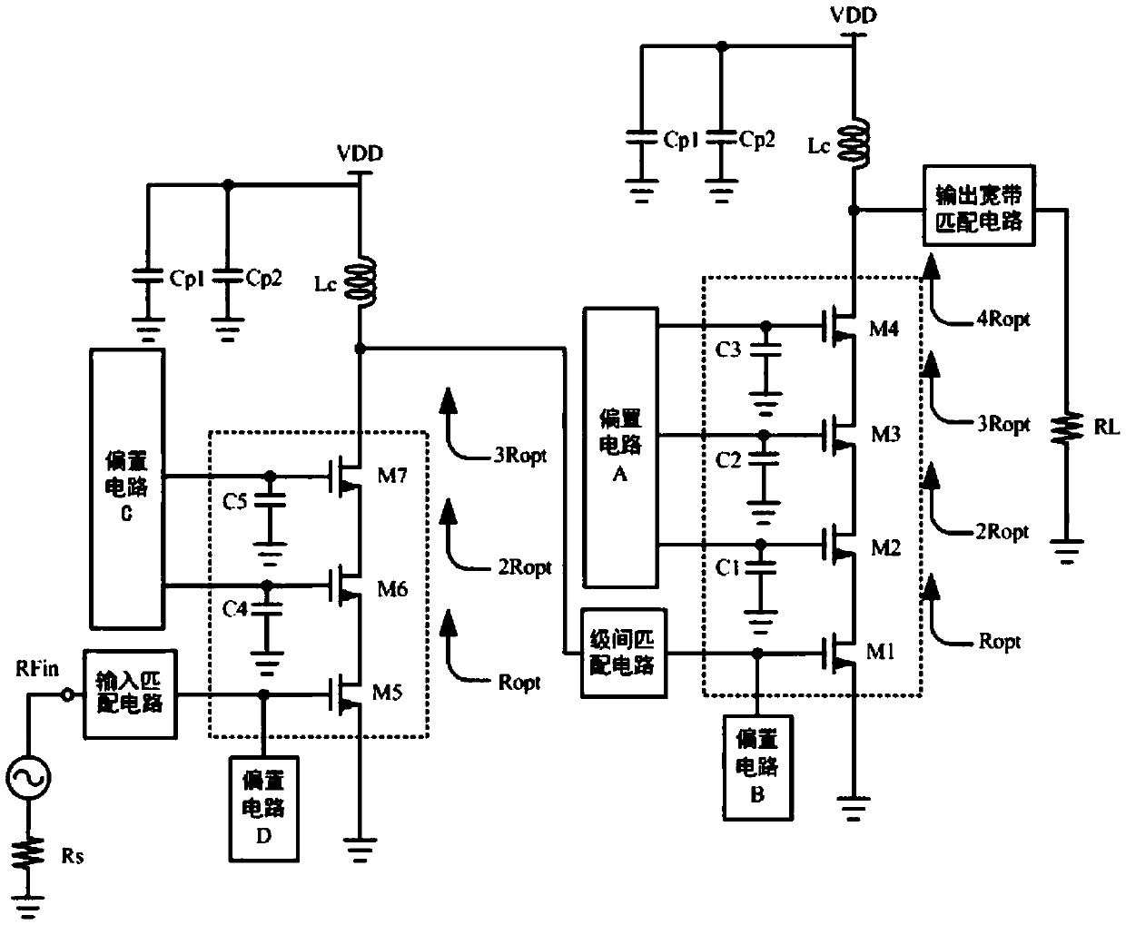
[0024] A preferred embodiment of the present invention, figure 1 As shown, a radio frequency power amplifier with a two-stage stacking structure, the radio frequency power amplifier includes an input matching circuit, an output broadband matching circuit, and a two-stage amplifier circuit formed by cascading an inter-stage matching circuit, and the two-stage amplifier circuit The front stage is the driver stage, and the latter stage is the power stage; the driver stage of the two-stage amplifier circuit includes: a power amplifier circuit connected and stacked by three transistor drains and sources, and the bias circuit C is connected to the power amplifier circuit The gates of M6 and M7 of the upper two transistors, the bias circuit D is connected to the gate of the lowest transistor M5, the gates of the upper two transistors M6 and M7 are grounded by connecting gate capacitors C4 and C5, and the lowest transistor The source of M5 is grounded; the power stage of the two-stage...


PUM


Abstract

The invention discloses a radio frequency power amplifier in a two-stage stack structure, comprising an input matching circuit, an output bandwidth matching circuit, and a two-stage amplifier circuit formed by cascading interstage matching circuits. A preceding stage of the two-stage amplifier circuit is a driving stage, and a following stage thereof is a power stage; a radio frequency signal source is connected with a gate electrode of a transistor in the bottommost layer of the driving stage through the input matching circuit, a drain electrode of a transistor in the uppermost layer of the driving stage is connected with one end of the corresponding interstage matching circuit, the other end of this interstage matching circuit is connected with a gate electrode of a transistor in the bottommost layer of the power stage, and a drain electrode of a transistor in the uppermost layer of the power stage is connected with a load through the output bandwidth matching circuit. This circuit enables improvements in the voltage withstand capacity, output voltage swing, operation bandwidth, power efficiency, power gain and maximum output power of the power amplifier and provides better harmonic suppression effect.

Description

technical field [0001] The invention relates to a power amplifier, in particular to a radio frequency power amplifier. Background technique [0002] As the key unit of the RF front-end in the transceiver, the RF power amplifier is an indispensable and important part of the modern wireless communication system. It is mainly used for the linear amplification of the RF signal and radiates it through the antenna. [0003] With the popularization of smart phones, mobile data is increasing exponentially. In order to meet the requirements of users' high-speed data experience, modern communication systems often use modulation methods with high spectral efficiency, such as QPSK and other modulation methods. This requires the application of new generation communication The system's RF power amplifier must have high power efficiency, linearity and bandwidth. In addition, in order to meet the usage requirements of users in different regions, mobile phones are generally required to supp...

Claims


Application Information

Patent Timeline
Patent Type & Authority Applications(China)
IPC IPC(8): H03F1/32H03F1/42H03F1/52H03F1/56H03F3/19H03F3/21H03F3/24
CPCH03F1/3205H03F1/42H03F1/523H03F1/56H03F3/19H03F3/21H03F3/245
Inventor 林俊明章国豪张志浩余凯黄敬馨区力翔
Owner GUANGDONG UNIV OF TECH
Why Eureka
Try Eureka