
Power compensation type workover rig power transmission system

A technology of power transmission system and power compensation, applied in mechanical equipment, spring mechanism, fluid pressure actuating device, etc., can solve problems such as poor matching and inability to provide constant pressure, so as to improve energy storage density and shorten charging energy. effect of time, volume reduction

Inactive Publication Date: 2016-04-27
JILIN UNIV
View PDF6 Cites 5 Cited by
  • Summary
  • Abstract
  • Description
  • Claims
  • Application Information

AI Technical Summary

Problems solved by technology

[0003] Among the existing energy storage equipment, the hydraulic accumulator has the advantages of high power density and high energy density, but it cannot provide constant pressure; the flywheel has good performance, but its charging and discharging cycle is poorly matched with the working conditions of the workover rig , both of which are difficult to use alone as energy storage equipment for workover rigs

Method used


Image

  • Power compensation type workover rig power transmission system
  • Power compensation type workover rig power transmission system
  • Power compensation type workover rig power transmission system

Examples


Embodiment Construction

[0023] specific implementation plan

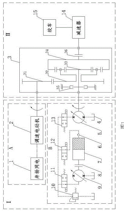
[0024] see figure 1 , in the power system A, the well site network power 1 drives the speed-adjusting motor 2 through a circuit connection, and inputs the power; It is connected with the speed reducer 14, and the sun gear 33 is connected with the variable pump-motor 5 through the locker 35, so as to realize the charging of the energy storage system B or the joint energy supply of the overall power system I; in the energy storage system B, the variable pump- The motor 5 is connected to the variable pump-motor 9 through the first electromagnetic switch valve 11 and the third electromagnetic switch valve 13, and the variable pump-motor 9 is connected to the flywheel hydraulic accumulator 7 through the clutch 8 to realize the mechanical path connection. The other end of the accumulator 7 is connected to the variable pump-motor 5 through the high-speed rotary joint 6, the second electromagnetic switch valve 12, and the third electromagnetic sw...


PUM


Abstract

The invention discloses a power compensation type workover rig power transmission system applying a flywheel-type hydraulic accumulator and belongs to the field of workover rig power transmission systems. The power compensation type workover rig power transmission system comprises a power system and a transmission system, the power system comprises an electrical power system and an energy storage system, the electrical power system comprises well field grid electricity and a variable-speed motor, the energy storage system comprises a hydraulic oil tank, a variable pump-motor, a high-speed joint, the flywheel-type hydraulic accumulator, a clutch, an overflow valve and an electromagnetic switching valve, and the transmission system comprises a coupler, a speed reducer and a winch. The well field grid electricity drives the variable-speed motor to output power, energy is charged into the flywheel-type hydraulic accumulator in the energy storage system via the coupler, or the well field grid electricity and the energy storage system supply energy in a combined manner, and the winch is driven to work after speed reduction and torque rise of the speed reducer. The power compensation type workover rig power transmission system has the advantages that the energy of the power system stems from the well field grid electricity, the energy storage system adopts the flywheel-type hydraulic accumulator as an energy storage device, deficiencies of grid electricity power are made up, and mode selection can be achieved according to a relation between required torque and output torque of the workover rig power transmission system, so that energy charging time is shortened, and energy use ratio is further increased.

Description

technical field [0001] The invention mainly relates to the field of power transmission system of a power compensation type workover rig, in particular to the power and transmission system of a power compensation type workover rig using a flywheel type hydraulic accumulator. Background technique [0002] The workover rig is an oilfield mechanical equipment for maintenance of the downhole pipe string or well body in the oil field. In order to achieve energy saving and environmental protection, the power system of the new workover rig uses the power grid of the well site instead of the diesel engine to supply energy. However, the power grid power of most oilfield sites is currently 30kW-50kW or so, which greatly limits the workover rig's operating capacity. In order to solve this problem, energy storage equipment is often added to the system and used together with the well site grid power. When the workover rig is in the unloading maintenance stage, the power demand is small, a...

Claims


Application Information

Patent Timeline
IPC IPC(8): B66D1/08B66D1/12B66D1/22B66D1/40F15B1/02
CPCB66D1/08B66D1/12B66D1/22B66D1/40F15B1/02F15B1/024
Inventor 王继新徐宁韩云武张宇汪柱锦蔡云光周君刘颖毅白雪
Owner JILIN UNIV
Features
  • Generate Ideas
  • Intellectual Property
  • Life Sciences
  • Materials
  • Tech Scout
  • Unparalleled Data Quality
  • Higher Quality Content
  • 60% Fewer Hallucinations
Learn More