A device for removing hydrogen fluoride in tail gas by using dynamic wave and its realization method

A realization method, dynamic wave technology, applied in chemical instruments and methods, separation methods, gas treatment, etc., can solve the problems of low absorption efficiency, difficult separation of sedimentation, nozzle clogging, etc., and achieve simple structure, less one-time investment, The effect of reducing clogging

Active Publication Date: 2018-03-27
ZHEJIANG AVILIVE CHEM CO LTD +1
View PDF7 Cites 0 Cited by
  • Summary
  • Abstract
  • Description
  • Claims
  • Application Information

AI Technical Summary

Problems solved by technology

This method generally adopts falling film absorption tower or packed tower to absorb hydrogen chloride, and uses calcium chloride as precipitant, but there are problems such as low absorption efficiency, clogging of nozzles and difficult separation of precipitates, etc.

Method used


Image

  • A device for removing hydrogen fluoride in tail gas by using dynamic wave and its realization method
  • A device for removing hydrogen fluoride in tail gas by using dynamic wave and its realization method

Examples


Embodiment 1

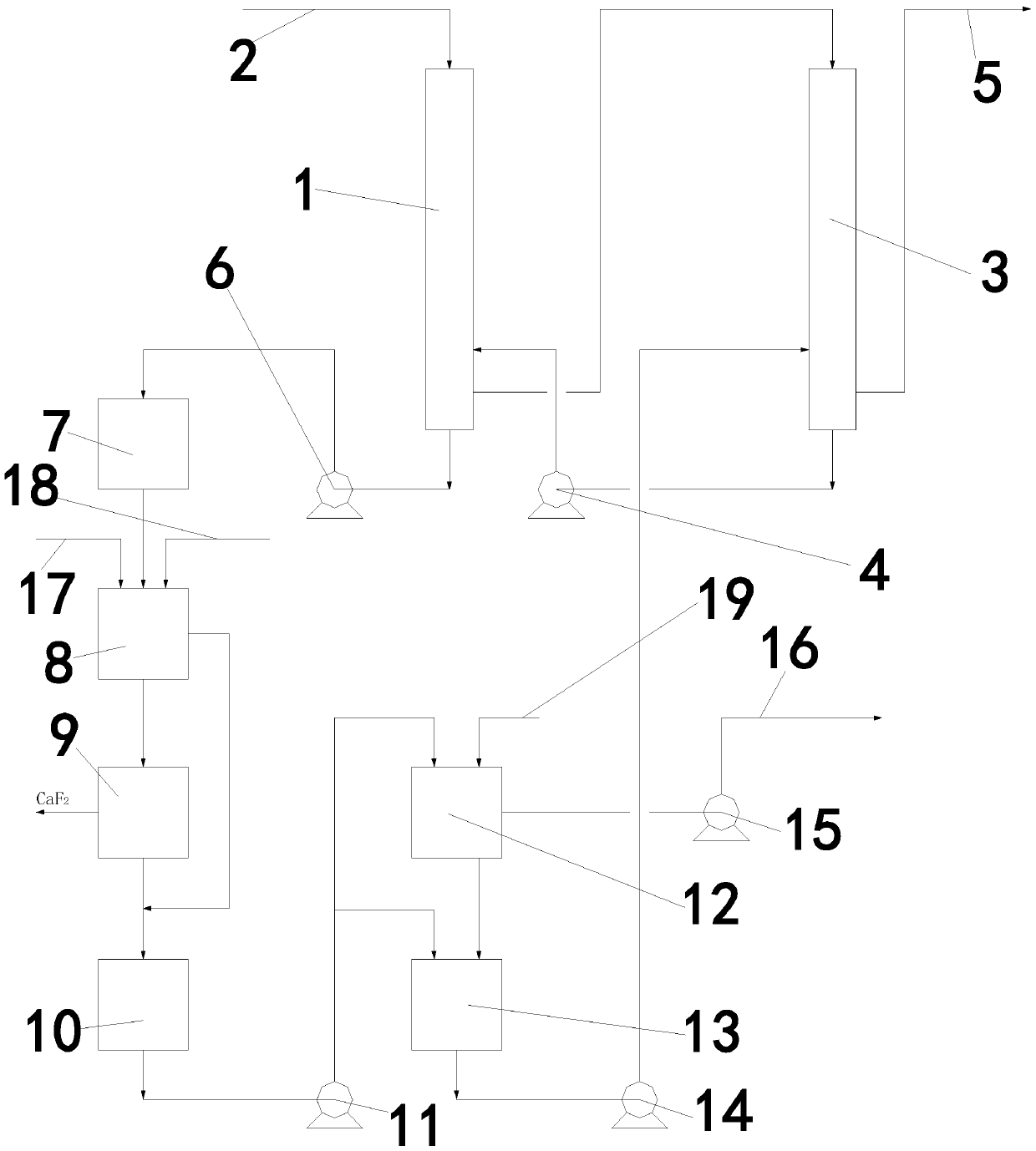
[0038] Such as figure 1 As shown, a device for removing hydrogen fluoride in tail gas by using dynamic wave, comprising a first-stage dynamic wave absorption tower 1, the top of the first-stage dynamic wave absorption tower 1 is provided with an exhaust gas inlet pipe 2, the first-stage dynamic wave absorption tower 1 and the second-stage The dynamic wave absorption tower 3 is connected, the first water pump 4 is provided between the primary dynamic wave absorption tower 1 and the secondary dynamic wave absorption tower 3, the exhaust gas output pipe 5 is arranged on the secondary dynamic wave absorption tower 3, and the primary dynamic wave absorption tower 3 is equipped with an exhaust gas output pipe 5. The absorption tower 1 is connected with the settling tank 7 by the second water pump 6, the settling tank 7 is connected with the filter press washing kettle 8, the filter press washing kettle 8 is connected with the centrifuge 9 and the mother liquor tank 10 respectively, a...

Embodiment 2

[0055] The differences between this embodiment and Embodiment 1 are: the fluorine-containing tail gas in this embodiment contains 5% hydrogen fluoride, the flow velocity of the absorption liquid nozzle is 30 m / s, the first-stage dynamic wave absorption tower 1 and the second-stage dynamic wave absorption The length of tower 3 is 8m; the height of the turbulence zone in the first-level dynamic wave absorption tower 1 and the second-level dynamic wave absorption tower 3 is 2.5m; the absorption liquid is a mixed solution of hydrogen chloride and calcium chloride, and the concentration of hydrogen chloride is 35%. The concentration of calcium chloride was 10%.


PUM

PropertyMeasurementUnit
lengthaaaaaaaaaa
heightaaaaaaaaaa

Abstract

The invention discloses a device for removing hydrogen fluoride from tail gas by virtue of dynamic waves. The device comprises a primary dynamic power absorption tower, wherein the primary dynamic wave absorption tower is connected with a secondary dynamic power absorption tower; a first water pump is arranged between the primary and secondary dynamic wave absorption towers; the primary dynamic power absorption tower is connected with a settling tank through a second water pump; the settling tank is connected with a filter pressing and washing kettle which is connected with a centrifuge and a mother liquor tank respectively; the centrifuge is connected with the mother liquor tank; the mother liquor tank is connected with a neutralizing tank and a circulating absorption liquid tank through a third water pump respectively; the neutralizing tank is connected with the circulating absorption liquid tank which is connected with the secondary dynamic wave absorption tower through a fourth water pump; the neutralizing tank is connected with a de-condensed calcium chloride pipe through a fifth water pump. The invention further discloses an implementation method for the device for removing the hydrogen fluoride from the tail gas by virtue of the dynamic waves. The device has the characteristics of simple structure, low construction cost, low production cost, high defluorination efficiency, low liquid-gas ratio, convenience for overhauling and the like.

Description

technical field [0001] The invention relates to tail gas treatment technology when trichloromethylpyridine and hydrogen fluoride are reacted to prepare trifluoromethylpyridine, in particular to a device for removing hydrogen fluoride in tail gas by using dynamic wave and its realization method. Background technique [0002] In the production process of synthesizing hydrofluorocarbons with chlorinated hydrocarbon compounds and hydrogen fluoride, the by-product hydrogen chloride contains a certain amount of hydrogen fluoride. Due to the existence of hydrogen fluoride, the application range of hydrogen chloride is limited. Therefore, the removal of hydrogen fluoride in the by-product hydrogen chloride is very important for the effective utilization of the by-product hydrogen chloride. [0003] At present, two kinds of fluoride removal methods are commonly used, namely dry separation method and wet separation method. Dry separation method is often used for defluorination of anh...

Claims


Application Information

Patent Timeline
Patent Type & Authority Patents(China)
IPC IPC(8): B01D53/78B01D53/68B01D53/96B01D53/73
CPCB01D53/68B01D53/73B01D53/78B01D53/96B01D2251/502B01D2257/2047
Inventor 李惠跃王凯泉金克强章建新
Owner ZHEJIANG AVILIVE CHEM CO LTD
Why Eureka
Try Eureka