
Current critical continuous unified control method for bidirectional DC-DC converter

A DC-DC, critical continuous technology, applied in the conversion of DC power input to DC power output, control/regulation systems, instruments, etc., can solve problems such as complex controller design

Active Publication Date: 2016-05-04
BEIJING INSTITUTE OF TECHNOLOGYGY
View PDF4 Cites 14 Cited by
  • Summary
  • Abstract
  • Description
  • Claims
  • Application Information

AI Technical Summary

Problems solved by technology

[0005] In order to overcome the above-mentioned commonly used dual active bridge bidirectional DC-DC converter controller design complex, reduce reactive power loss and conduction loss and other related problems, the present invention discloses a bidirectional DC-DC converter current critical continuous The unified control method, the technical problem to be solved is to provide a dual active bridge bidirectional DC-DC converter current critical continuous unified control method for the topology of commonly used types of bidirectional DC-DC converters, reducing the reactive power of the circuit Loss, reduce the current stress of the switch tube and the circulation loss of the converter, improve the efficiency and reliability of the converter; at the same time, it can greatly reduce the complexity of the control unit

Method used


Image

  • Current critical continuous unified control method for bidirectional DC-DC converter
  • Current critical continuous unified control method for bidirectional DC-DC converter
  • Current critical continuous unified control method for bidirectional DC-DC converter

Examples


Embodiment 1

[0044] Taking the control of a bidirectional DC-DC converter of a commonly used type as an example to illustrate the realizability and beneficial effects of a current critical continuous unified control method for a bidirectional DC-DC converter disclosed in the present invention.

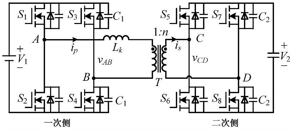
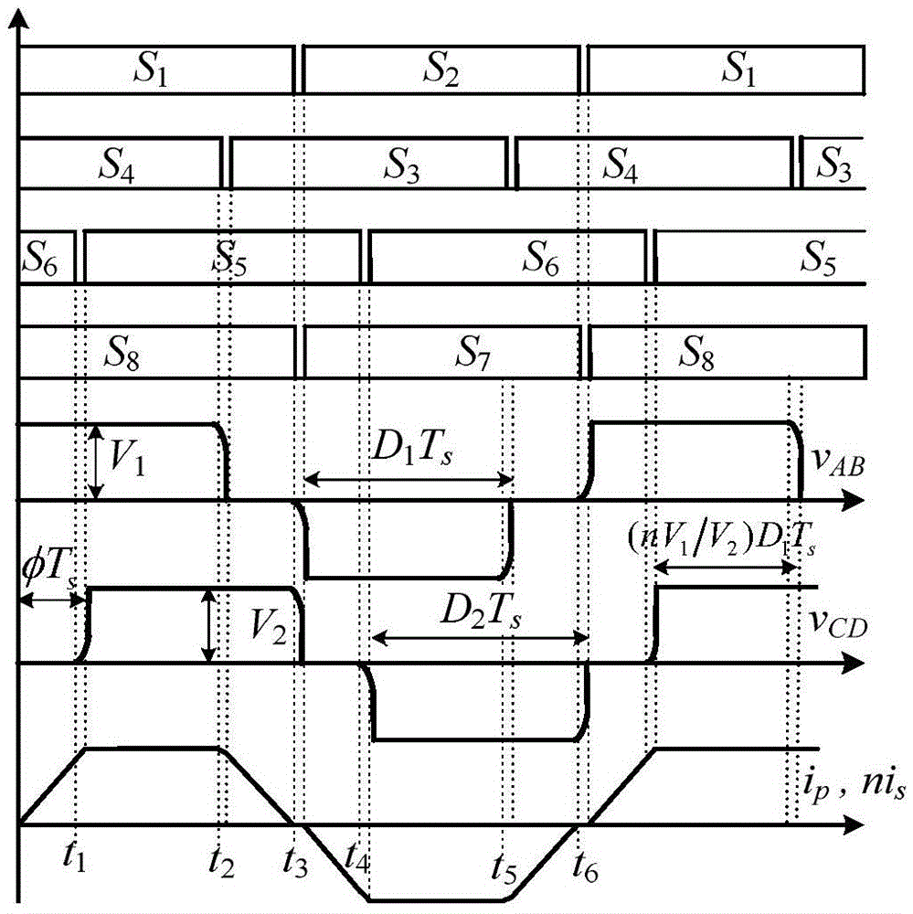
[0045] Commonly used types of dual active bridge bidirectional DC-DC converters are attached figure 1 shown. As shown in the figure, the converter is a bidirectional dual active bridge DC-DC converter, the primary side is an active full bridge circuit, and the secondary side is also an active full bridge circuit. Points A and B are the respective midpoints of the two bridge arms of the primary side active bridge; C and D points are the respective midpoints of the two bridge arms of the secondary side active bridge; v AB is the voltage difference between point A and point B; v CD is the voltage difference between points C and D. i p and i s It is the current of the transformer primary side and ...


PUM


Abstract

The invention discloses a current critical continuous unified control method for a bidirectional DC-DC converter, relates to a current critical continuous unified control method for a dual-active bridge bidirectional DC-DC converter, and belongs to the field of power electronics. According to the control method disclosed by the invention, voltages on a primary side and a secondary side of a transformer and a phase difference between the voltages are controlled to make the converter work in a transformer current critical continuous mode and reduce the ring current and conduction loss of the converter. In addition, a transformer current can be enabled to be in a critical continuous mode through a boundary condition and a control condition, so that the reactive loss of a circuit is reduced, the current stress of a switching tube and the ring current loss of the converter are reduced, and the efficiency and reliability of the converter can be improved. The method further can greatly lower the complexity of a control unit and realize real-time control. The method can be applied to high-frequency isolation switching power supplies.

Description

technical field [0001] The invention relates to a current critical continuous and unified control method of a bidirectional DC-DC converter, in particular to a current critical continuous and unified control method of a dual active bridge bidirectional DC-DC converter, belonging to a high-frequency isolated switching power supply in the field of power electronics direction. Background technique [0002] With the development of power electronics technology, the demand for bidirectional, high-frequency isolation, and high-efficiency converters is gradually increasing, especially in various power supply systems such as solid-state transformers including energy storage units, high-voltage direct current transmission, and micro-grids. These systems require the converter to have the characteristics of bidirectional controllable power flow due to the need for energy control of charging and discharging the energy storage unit. In addition, high transfer efficiency can improve the p...

Claims


Application Information

Patent Timeline
IPC IPC(8): H02M3/335
CPCH02M3/3353H02M3/33592
Inventor 沙德尚许国张健坤
Owner BEIJING INSTITUTE OF TECHNOLOGYGY
Learn More