
Control chip for LED (Light-Emitting Diode) driving

An LED driving and control chip technology, applied in the field of lighting, can solve the problems of increasing the energy consumption of the driving circuit, the large volume of the transformer, and the disadvantage of miniaturization, and achieve the effects of high stability, simple structure and small volume

Inactive Publication Date: 2016-05-04
FOSHAN CITY NANHAI DISTRICT LIANHE GUANGODNG XINGUANGYUAN IND INNOVATION CENT
View PDF2 Cites 7 Cited by
  • Summary
  • Abstract
  • Description
  • Claims
  • Application Information

AI Technical Summary

Problems solved by technology

Generally speaking, due to the addition of a transformer, the efficiency of the isolated power supply will be reduced, usually about 88%, and the volume of the transformer is relatively large, which is not conducive to the miniaturization of LEDs.
Moreover, in order to ensure constant current and constant voltage, the current isolated drive circuit needs to adopt secondary feedback and loop compensation, which increases the energy consumption of the drive circuit

Method used

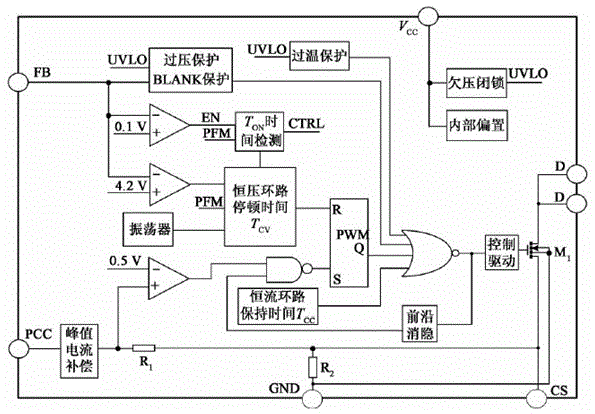

Image

  • Control chip for LED (Light-Emitting Diode) driving
  • Control chip for LED (Light-Emitting Diode) driving
  • Control chip for LED (Light-Emitting Diode) driving

Examples


Embodiment 1

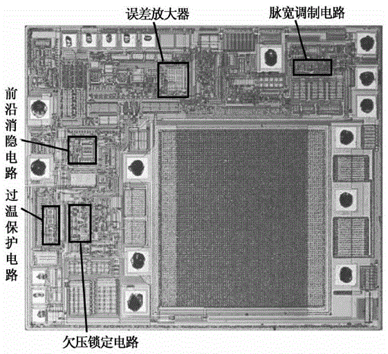
[0027] The chip layout of this implementation is as follows figure 2 As shown, the BCD1.5μm process is adopted, the chip size is 2.00mm×2.04mm, double-layer Al double-layer polycrystalline.

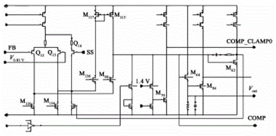
[0028] Wherein, the error amplification module circuit of the chip is as follows image 3 shown. The voltage at COMP is clamped high at 1.4V+Vgs. When the COMP voltage does not reach 1.4V+V gs When the COMP_CLAMP0 output is high level; when the COMP voltage reaches 1.4V+V gs , COM_CLAMP0 output is low level. The output of the error amplifier V out is clamped high at 1.4V. M64 and M62 have the same size, when the voltage at COMP has not risen to the NMOS tube voltage V th when M 64 with M 62are not turned on, V out The voltage is 0. m 62 The drain terminal voltage is high level, through the pull-down tube, the M 136 The source terminal voltage is pulled down to ground, then M 117 The current increases through the mirror, M 115 Charge the COMP, the COMP voltage is clamped lo...


PUM


Abstract

The invention generally relates to a lighting technology, in particular to a control chip for LED (Light-Emitting Diode) driving. The chip comprises an error amplification module, a pulse width modulation module, a leading edge blanking module, an over-temperature protection module, and an under voltage lockout module, wherein the error amplification module enables a difference between a reference voltage of an in-phase inputting terminal and a feedback voltage of an inverting inputting terminal in the chip to be amplified; the pulse width modulation module enables the chip to achieve PWM (Pulse Width Modulation) logic control and enables a circuit to output a gate-driving signal of a power switch; the leading edge blanking module enables the chip circuit to eliminate a pulse peak current generated at the moment that the switch is conducted; the over-temperature protection module enables the chip to achieve a hysteresis function when a temperature is risen to an excessively high temperature; and the under voltage lockout module detects whether a voltage of a built-in analog voltage drain drain AVDD of the chip circuit reaches a threshold and outputs a response detection signal UVLO (under voltage lockout). Compared with the prior art, the control chip has the advantages that constant-voltage constant-current loop control is adopted; a loop can be stabilized in a primary side feedback mode; the control chip is simple in structure and small in volume; and an integral system can have high stability without secondary feedback or loop compensation.

Description

technical field [0001] The present invention generally relates to a lighting technology, in particular to a control chip for driving LEDs. Background technique [0002] LED has many advantages such as high luminous efficiency, long life, fast response, low operating cost, and environmental protection. With the rapid development of semiconductor core devices and related supporting technologies, LEDs are increasingly used in lighting and other fields. Since the light-emitting principle of LED is to use a solid semiconductor chip as a light-emitting material, after applying a forward voltage to both ends of the semiconductor chip, the minority interceptors and the majority interceptors in the semiconductor recombine, releasing excess energy and causing photon emission. Directly emit red, orange, yellow, green, blue, blue, purple, and white light, so the LED drive circuit needs to maintain constant current or even constant voltage. Generally speaking, when the power supply vo...

Claims


Application Information

Patent Timeline
IPC IPC(8): H05B33/08H05B44/00
CPCH05B45/10H05B45/44H05B45/37Y02B20/30
Inventor 不公告发明人
Owner FOSHAN CITY NANHAI DISTRICT LIANHE GUANGODNG XINGUANGYUAN IND INNOVATION CENT
Learn More