
Comprehensive treatment method for boiler smoke

A boiler flue gas and comprehensive treatment technology, applied in separation methods, chemical instruments and methods, and separation of dispersed particles, can solve the problems of high cost and high resource consumption, reduce desulfurization costs, save desulfurization water, and be of great social importance. benefit effect

Inactive Publication Date: 2016-05-11
南京金羚生物基纤维有限公司
View PDF0 Cites 2 Cited by
  • Summary
  • Abstract
  • Description
  • Claims
  • Application Information

AI Technical Summary

Problems solved by technology

[0002] The flue gas emitted by the current coal-fired boilers contains a certain amount of sulfur dioxide. At present, the commonly used desulfurization methods include limestone desulfurization, double-alkali desulfurization and ammonia desulfurization. These desulfurization methods need to consume more resources and cost. Higher. At present, some enterprises have a large number of mixed liquids generated by treating waste gas containing hydrogen sulfide. These mixed liquids contain a certain amount of sodium hydrosulfide and sodium sulfide. If fresh sodium hydroxide solution is used to treat hydrogen sulfide waste gas, The resulting mixed solution can be used to make sodium hydrosulfide slices, but some enterprises will produce a large amount of waste lye due to the process requirements in production. The waste lye contains a certain amount of sodium hydroxide and a large amount of impurities , these enterprises will use these waste lye to treat hydrogen sulfide-containing waste gas, and the mixed liquid generated by using waste lye to treat hydrogen sulfide-containing waste gas is not suitable for making sodium hydrosulfide slices. How to deal with these mixed liquids containing a large amount of impurities is also a business problem

Method used


Image

  • Comprehensive treatment method for boiler smoke

Examples


specific Embodiment

[0024] In order to describe the present invention in detail, the following will be specifically described in conjunction with the device using the present invention.

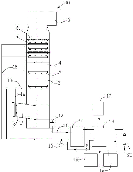
[0025] refer to figure 1 In the tower inner chamber 2 of the desulfurization tower 30, an inner chamber sprayer 7 for spraying desulfurization liquid is installed, and a flap demister 6 and a swirl plate demister are installed on the upper part of the tower inner chamber 2 of the desulfurization tower 30. The fogger 4 is equipped with a cleaner 5 for cleaning the folded plate demister 6 on the upper and lower sides of the folded plate demister 6. The lower part of the desulfurization tower 30 has a flue gas inlet channel 1 and a gray water outlet 12. The upper part of 30 has a flue gas outlet passage 8, and the gray water outlet 12 is connected to the buffer tank 9 through the return pipe 11, and the buffer tank 9 is respectively connected to the desulfurization tank 16 and the flotation tank 18 through the pipe...


PUM


Abstract

A comprehensive treatment method for boiler smoke includes the following steps that firstly, a desulphurization solution containing sodium hydrosulfide and sodium sulfide in a desulphurization tank is pumped into an inner cavity of a desulphurization tower through a desulphurization pump; secondly, sulfur dioxide in the smoke and sodium hydrosulfide and sodium sulfide in the desulphurization solution are reacted in the inner cavity of the desulphurization tower, and the reacted desulphurization solution drops into the lower part of the desulphurization tower and then flows into a buffer tank through a lye outlet; thirdly, an upper-layer solution of the desulphurization solution in the buffer tank flows into the desulphurization tank. According to the method, when the boiler smoke is desulfurated, the solution containing sodium hydrosulfide and sodium sulfide is treated at the same time; by means of the method, existing boiler smoke desulphurization equipment can be refitted without building new desulphurization equipment; by adopting the solution containing sodium hydrosulfide and sodium sulfide for removing sulfur dioxide in the boiler smoke, a lot of desulphurization water can be saved, the flue gas desulphurization cost is lowered, the effect of treating waste with waste is achieved, and great social benefits are achieved.

Description

technical field [0001] The invention relates to a method for treating boiler flue gas. Background technique [0002] The flue gas emitted by the current coal-fired boilers contains a certain amount of sulfur dioxide. At present, the commonly used desulfurization methods include limestone desulfurization, double-alkali desulfurization and ammonia desulfurization. These desulfurization methods need to consume more resources and cost. Higher. At present, some enterprises have a large number of mixed liquids generated by treating waste gas containing hydrogen sulfide. These mixed liquids contain a certain amount of sodium hydrosulfide and sodium sulfide. If fresh sodium hydroxide solution is used to treat hydrogen sulfide waste gas, The resulting mixed solution can be used to make sodium hydrosulfide slices, but some enterprises will produce a large amount of waste lye due to the process requirements in production. The waste lye contains a certain amount of sodium hydroxide and ...

Claims


Application Information

Patent Timeline
IPC IPC(8): B01D53/78B01D53/50
Inventor 程虎得
Owner 南京金羚生物基纤维有限公司
Features
  • Generate Ideas
  • Intellectual Property
  • Life Sciences
  • Materials
  • Tech Scout
  • Unparalleled Data Quality
  • Higher Quality Content
  • 60% Fewer Hallucinations
Learn More