Composite phase change heat exchange device for boiler flue gas waste heat recovery

A composite phase conversion heat and waste heat recovery technology, which is applied in the field of equipment in the field of boiler heat transfer technology, can solve problems such as difficulties in the evaporation section of heat exchange circular tubes, achieve flexible adjustment methods, reduce failure rates, and ensure safe operation.

Inactive Publication Date: 2012-03-28
王海波
View PDF8 Cites 3 Cited by
  • Summary
  • Abstract
  • Description
  • Claims
  • Application Information

AI Technical Summary

Problems solved by technology

[0010] The purpose of the present invention is to solve the problems existing in the above-mentioned prior art, to eliminate the defect of GGH by using the clean flue gas after the desulfurization of the hot air, and to solve the difficult problem of arranging the heat exchange circular tube evaporation section in the vertical flue or inclined flue , and the problem that the evaporating section and the condensing section of the phase-change heat exchanger must be arranged separately, realize the integrated and compact arrangement of the evaporating section and the condensing section of the phase-change heat exchanger, and realize a truly integrated composite phase-change heat exchanger. Effectively reduce the flue gas temperature in front of the desulfurization tower, save desulfurization water, and reduce the harm of low-temperature corrosion, so as to achieve the goals of energy saving, water saving and emission reduction

Method used


Image

  • Composite phase change heat exchange device for boiler flue gas waste heat recovery
  • Composite phase change heat exchange device for boiler flue gas waste heat recovery
  • Composite phase change heat exchange device for boiler flue gas waste heat recovery

Examples


Embodiment 1

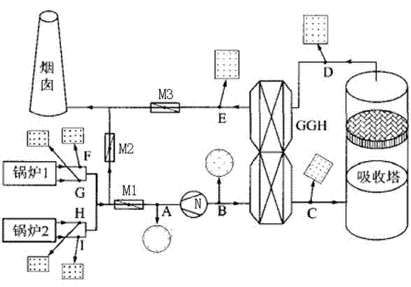
[0060] Composite phase conversion heat device for waste heat recovery of boiler flue gas (see attached Figure 5 and accompanying drawings), using air as the working medium for recycling waste heat, including the boiler flue, internal and external equipment of the flue, its connecting pipes, and control instrument valves. The flue is equipped with a class I composite phase change heat exchanger 24, a stage II composite phase change heat exchanger 29, a supporting control system, a mixing chamber 31, and the boiler’s original economizer 22 and air preheater 23. Dust collector 26, desulfurization tower 30, etc. Outside the flue, a Class I temperature regulation system 35, a Class II temperature regulation system 40, a Class I pump 33, a heat exchanger 34, a Class II pump 39, and matching automatic control devices 36, supporting pipes, instrument valves, etc. are arranged. Part of the hot air 42 from the air preheater 23 flows out, and is sent to the mixing chamber 31 through th...

Embodiment 2

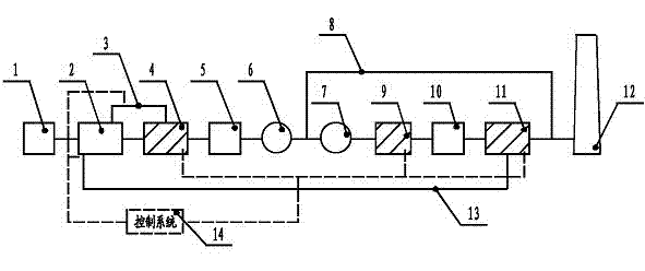
[0079] Composite phase conversion heat device for waste heat recovery of boiler flue gas (see attached Image 6 and description of the accompanying drawings), the device is also provided with a box 24-6 between the tube sheets in the I-stage composite phase-change heat exchanger 24; the II-stage composite phase-change heat exchanger is also provided with a box 29 between the tube sheets -6. This structure is suitable for flue gas in the tube side of the inner heat exchange tube, phase change working fluid in the casing side, and the cold fluid in the shell layer is liquid. For the shell side, the cold fluid 37 such as water, heat transfer oil or other suitable process medium is used as the medium for waste heat recovery. See Embodiment 1 for other specific implementation methods.

Embodiment 3

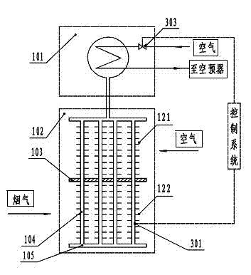
[0081] Composite phase conversion heat device for waste heat recovery of boiler flue gas (see attached Figure 7 and accompanying drawings), for boilers without desulfurization devices, the second-stage composite phase change heat exchanger 29 is used to continue to recover the waste heat of the flue gas. Since dew condensation may occur, a mixing chamber 31 is still installed and heated by the air preheater Part of the hot air 42 flows out from the hot air pipe 42-1 to the mixing chamber 31, where it is uniformly mixed with the outlet flue gas of the second-stage composite phase change heat exchanger 29 to avoid condensation, and then discharged into the air through the chimney. atmosphere. Refer to Embodiment 1 or Embodiment 2 for other specific implementation methods.


PUM


Abstract

The invention discloses a composite phase change heat exchange device for boiler flue gas waste heat recovery. The device comprises an original flue internal device of a boiler, an original flue external device of the boiler, a connecting pipeline of the original flue internal device of the boiler and the original flue external device of the boiler and a control meter valve; and a flue duct is internally provided with one or more than one level-I composite phase change heat exchanger, one or more than one level-II composite phase change heat exchanger and a mixing chamber as well as a matched temperature regulating system and an automatic control device which arte arranged outside the flue duct. According to the invention, through phase change working media between a heat exchange pipe and a sleeve pipe in the composite phase change heat exchanger, the combination of an evaporator and a condenser in one device is realized, the efficient recovery of flue gas exhaust heat is realized, a great amount of water for desulfurization is saved, and the low-temperature corrosion of the flue gas is reduced; and simultaneously, the hot air which is heated by an air preheater is utilized to be partially separated out so as to be mixed with net flue gas after desulfurization and is subjected to temperature rise, the mixed air is emitted into atmosphere after reaching the flue gas emission requirement, the low-temperature corrosion of a net flue gas heater after a wet desulfurization is avoided radically at present, and the damage to the environment caused by the flue gas is relieved.

Description

technical field [0001] The invention relates to a device in the technical field of boiler heat transfer, in particular to a composite phase-change heat device for boiler flue gas waste heat recovery. Background technique [0002] At present, more than 80% of domestic thermal power plants use gas-gas heat exchangers (GGH for short) in the wet flue gas desulfurization (Flue Gas Desulfurization, referred to as FGD). , the direct equipment cost of installing GGH is about 1.1 billion yuan. Other related costs include: increased booster fan due to the installation of GGH, increased control points of the control system, increased flue length, GGH support and corresponding building installation costs, etc., the sum of which accounts for about 15% to 20% of the total investment of FGD . The pressure drop of flue gas when GGH is installed is about 1200Pa. In order to overcome these resistances, the pressure head of the booster fan must be increased, which greatly increases the opera...

Claims


Application Information

Patent Timeline
Patent Type & Authority Applications(China)
IPC IPC(8): F23J15/08F23L15/00
CPCY02E20/34
Inventor 王海波董立军尹旭杰王海军
Owner 王海波
Why Eureka
Try Eureka