

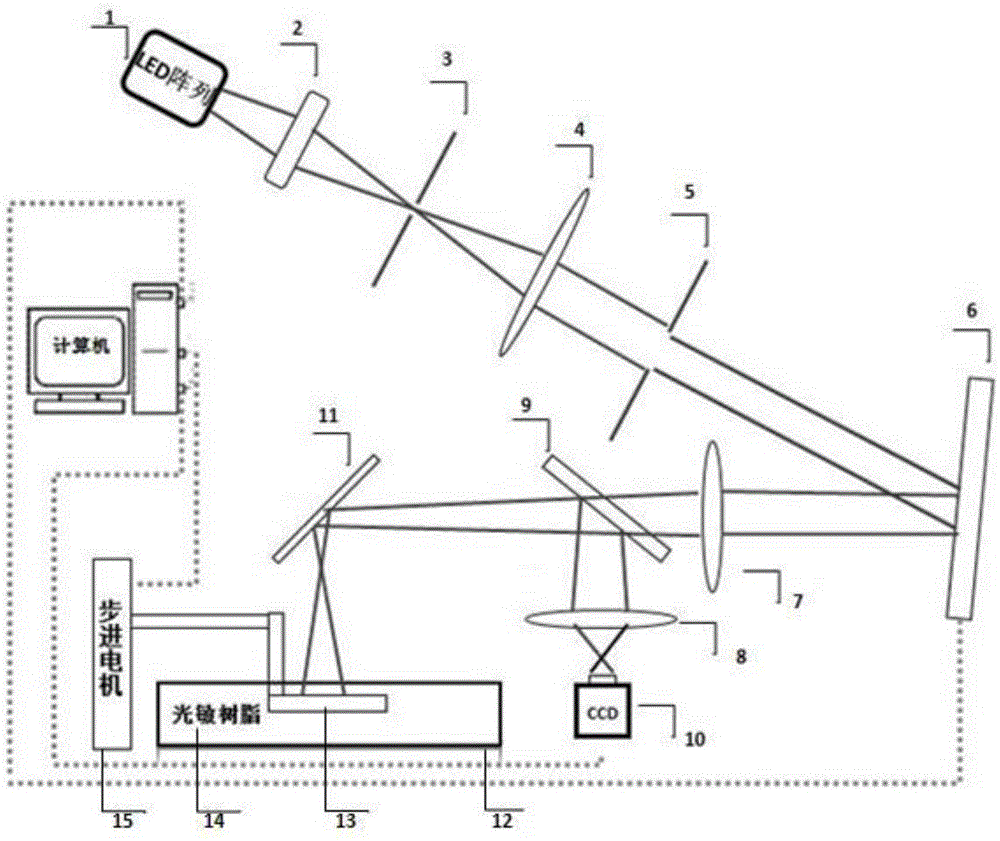
Method for manufacturing three-dimensional photonic crystal templates on basis of micro-projection 3D (three-dimensional) printing
A photonic crystal and 3D printing technology, applied in optics, optical components, instruments, etc., can solve the problems that cannot meet the requirements of the three-dimensional structure of the special geometric shape channel, achieve low production cost, high degree of customization, and reduce printing time Effect
- Summary
- Abstract
- Description
- Claims
- Application Information
AI Technical Summary
Problems solved by technology
Method used
Image


Examples
Embodiment 1
[0037] Taking the preparation of a tiny wood-packed three-dimensional photonic crystal template with chiral channels as an example, the steps are as follows:
[0038] (1) Use the 3D model-aided design software to design a tiny wooden model with chiral channels, as shown in the figure. The structure is composed of a number of identical cuboid rods arranged periodically, and the cross-sectional width of each rod is 0.15mm*0.15mm, the number of periods in the x-y-z directions is 15*15*5, the overall size is about 5mm*5mm*3mm, and a chiral channel is designed in the center of the model, and the size is about 0.16mm*0.16mm.
[0039] (2) The model is output as a 3D model file and input into the slicing software to cut the 3D photonic crystal model into several 2D black and white images, (such as figure 2 The white area represents the cross-section of the model, in which there is a small groove in the middle of the central rod, and multiple small grooves are arranged helically along...
Embodiment 2
[0049] Taking the wood-stacked three-dimensional photonic crystal template with a complete cycle as an example, the overall design of the model is the same as in Example 1, and its complete cycle is reflected in the fact that the model is composed of a number of completely identical cuboid rods arranged periodically, and there is no spiral upward Chiral channels or other defects. The preparation steps are the same as in Example 1.
PUM
 Abstract
Description
Claims
Application Information