An energy-storage micro-head fluid energy pumping system using solar pressurization

A technology of solar energy and fluid energy, applied in solar heating systems, solar thermal energy, solar thermal power generation, etc., can solve problems such as difficult, slow, and unrealistic pumping, and achieve the effect of solving slow pumping, ensuring full utilization, and increasing power

Active Publication Date: 2017-12-12
ANHUI JINSANHUAN METAL SCI & TECH
View PDF1 Cites 0 Cited by
  • Summary
  • Abstract
  • Description
  • Claims
  • Application Information

AI Technical Summary

Problems solved by technology

[0002] The traditional way of pumping water is to use electric energy or the energy generated by fuel combustion as the power energy of the pumping device to drive the pumping device to achieve pumping. In this process, a lot of traditional energy will be wasted.
Moreover, in many remote places, it is difficult to supply electric energy, and it is difficult to transport traditional fuel oil. It is obviously unrealistic to use the traditional method to pump water. Therefore, if the potential energy of water can be used to realize water pumping, it will have broad prospects
At present, there is a type of pumping system that uses water flow to generate electricity, and then uses electric power to drive the water pump to pump water. This method can be realized for large rivers or water flows with obvious drops, but for water flows with gentle water flow and small water flow drops, this type of system Due to the low power generation efficiency, it is difficult to achieve the expected power generation purpose
Another type of pumping system directly uses the water flow to drive the pump to pump water, which is also difficult to overcome the shortcomings of being powerless in the face of a gentle water flow and a small water drop.
At present, although some pumping systems use the speed change mechanism to increase the speed obtained by the energy harvesting mechanism from the gentle water flow to drive the water pump to pump water, or use the water hammer pump to secondarily pressurize the water flow, etc., the use of micro-head fluid pumping is realized. functions, but such systems still have disadvantages such as low pumping efficiency
[0003] The patent application No. 201310649113.X published on March 5, 2014 discloses an energy storage micro-head fluid energy pumping system. This system not only overcomes the shortcomings of traditional pumping systems that require electricity or fuel as a power source, It solves the problem of difficulty in pumping water in special areas, and also overcomes the shortcomings of traditional water pumps that use water to pump water that are difficult to use micro-heads as a power source, and because it uses an air storage cylinder as an energy storage power source, it greatly improves its working efficiency. It solves the shortcomings of the traditional micro-head pumping system, such as slow water pumping and poor instantaneous power, but because only the micro-head drives the air pump to inflate the air storage pump to store energy, and then the gas in the air storage pump drives the water hammer pump to pump water. When the water flow is high It is difficult to exert good efficiency when the volume of the air storage pump is small and the volume is limited

Method used


Image

  • An energy-storage micro-head fluid energy pumping system using solar pressurization
  • An energy-storage micro-head fluid energy pumping system using solar pressurization
  • An energy-storage micro-head fluid energy pumping system using solar pressurization

Examples


Embodiment Construction

[0034] The present invention will be further described below in conjunction with the examples and accompanying drawings, because the following description is only a specific embodiment of the present invention, but the protection of the present invention is not limited thereto, and any changes or substitutions conceived by those skilled in the art are all covered within the protection scope of the present invention.

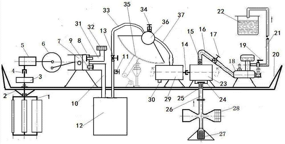
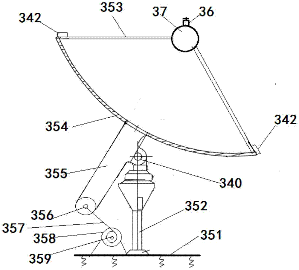
[0035] Such as Figures 1 to 3 As shown, an energy-storage micro-head fluid energy pumping system using solar energy supercharging, the system consists of a fluid energy harvesting mechanism 1, a speed change mechanism 5, a crank linkage mechanism 6, a plunger type air pump 7, an air storage tank 12, and an air pressure motor 30. Rotor type water pump 23, water hammer pump 18, solar tracking system 35, gas heating chamber 36 and pipelines, wherein the fluid energy harvesting mechanism 1 is connected to the speed change mechanism 5, and the speed change mechanism ...


PUM


Abstract

A solar pressurized energy storage type micro waterhead fluid energy water pumping system is composed of a fluid energy extraction mechanism, a speed change mechanism, a crank-link mechanism, a plunger type gas pump, a gas reservoir, a pneumatic motor, a rotor type water pump, a hydraulic ram, a solar tracing system, a gas heating cavity and a pipeline. The fluid energy extraction mechanism is connected with the speed change mechanism which is connected with the plunger type gas pump through the crank-link mechanism. A gas pump gas outlet pipe of the plunger type gas pump is connected with the gas reservoir. A gas reservoir gas outlet pipe of the gas reservoir is connected with the gas heating cavity formed in the solar tracing system. The gas heating cavity is connected to the pneumatic motor through a cavity body gas outlet pipe. A power output shaft of the pneumatic motor is connected with the rotor type water pump. A water pump water outlet of the rotor type water pump is connected with the hydraulic ram. A curved mirror is arranged on the solar tracing system. Sunlight irradiated to the curved mirror is reflected to the gas heating cavity by the curved mirror and is used for heating gas in the gas heating cavity.

Description

technical field [0001] The invention relates to a pumping system, in particular to an energy-storage micro-head fluid energy pumping system using solar pressurization, and belongs to the fields of energy saving, environmental protection and mechanical design. Background technique [0002] The traditional way of pumping water is to use electric energy or the energy generated by fuel combustion as the power source of the pumping device to drive the pumping device to achieve pumping. In this process, a lot of traditional energy is wasted. Moreover, in many remote places, electricity is difficult to supply, and traditional fuel is difficult to transport. It is obviously unrealistic to use traditional methods to pump water. Therefore, it will have broad prospects if the potential energy of water can be used to pump water. At present, there is a type of pumping system that uses water flow to generate electricity, and then uses electric power to drive the water pump to pump water. ...

Claims


Application Information

Patent Timeline
Patent Type & Authority Patents(China)
IPC IPC(8): F04B23/10F04B23/02F24J2/10F24J2/38E03B5/00F24S23/70F24S50/20
CPCE03B5/00F04B23/028F04B23/10F24S23/70F24S50/20F24S2023/832Y02A20/00Y02E10/47
Inventor 邵作权
Owner ANHUI JINSANHUAN METAL SCI & TECH
Why Eureka
Try Eureka