Boiler flue gas waste heat circulating heat-supply system

A boiler flue gas and heating system technology, applied in heating systems, hot water central heating systems, household heating, etc., can solve problems such as low fuel consumption and recovered steam, insufficient heat exchange, and waste of heat energy. Achieve the effect of reducing maintenance cost, increasing service life and reducing maintenance amount

Active Publication Date: 2016-05-11
HEBEI UNIV OF TECH
View PDF6 Cites 6 Cited by
  • Summary
  • Abstract
  • Description
  • Claims
  • Application Information

AI Technical Summary

Problems solved by technology

[0003] However, the existing recovery device will lead to the existence of waste heat, and the recovery is not comprehensive, and there is a lot of waste when the waste heat is recovered. For example, the ZSHH-A heat pipe waste heat recovery device (air-water), the lower part is the flue, and the upper part is the water tank. There is a partition in the middle, a safety valve, a pressure gauge, and a temperature gauge interface on the top, and the water tank has an inlet and outlet and a sewage outlet. The disadvantage is that there is only water and heat exchange during the recovery process, and the part contained in the flue gas is not completely released. The heat energy of the heat pipe cannot be utilized, resulting in waste of heat energy. At the same time, this process cannot realize secondary recovery, and at the same time, it lacks the treatment of exhaust gas; The baffle separates the passages on both sides, the heat pipe is a full-finned tube, and a single heat pipe can be replaced. The exhausted flue gas contains some heat, and the temperature of the waste heat recovery cannot be monitored anytime and anywhere, and the water temperature can only be controlled by adjusting the amount of flue gas in and out; the incineration of the tail gas recovery system of Nanjing Yire Zonglian Technology Co., Ltd. The furnace has a unique structure of zoom tube type, the flame distribution is uniform, the air flow is violently disturbed, and the material is completely burned. The amount of recovered steam is low, which cannot meet the production demand

Method used


Image

  • Boiler flue gas waste heat circulating heat-supply system

Examples


Embodiment 1

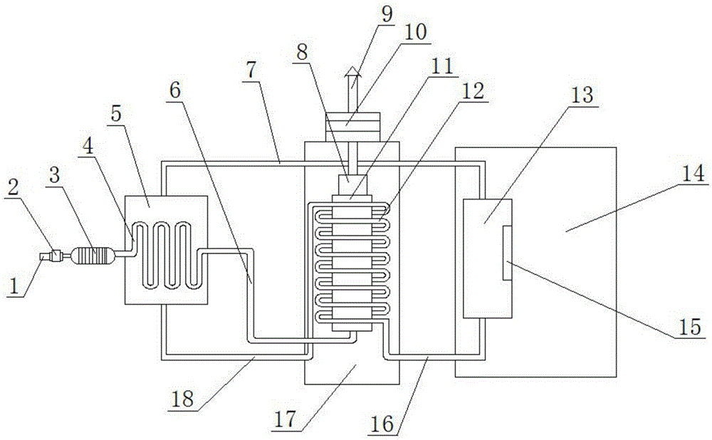
[0026] The boiler flue gas waste heat circulation heating system in this embodiment includes an intake pipe 1, a blower 2, a dust removal device 3, a boiler flue gas waste heat heating box 5, an air outlet pipe 6, a cold water pipe 7, a chimney 9, a drying device 10, and a hot water circulation Heating pipeline 12, hot water tank 13, hot water pipeline 16, catalytic heating device 17 and water outlet pipeline 18; Described air blower 2 is provided with catalyst, and the air inlet end of air blower 2 is connected air inlet pipeline 1, and air outlet end and dedusting device 3 One end of the boiler flue gas waste heat heating box 5 is provided with a curved flue gas heating pipe 4, one end of the curved flue gas heating pipe 4 is connected to the other end of the dust removal device 3, and the curved flue gas heating pipe 4 The other end is connected to one end of the gas outlet pipeline 6; the water inlet of the boiler flue gas waste heat heating box 5 is connected to one end of...


PUM


Abstract

The invention relates to a boiler flue gas waste heat circulating heat-supply system. The boiler flue gas waste heat circulating heat-supply system is characterized by comprising an air inlet pipeline, an air blower, a dust removal device, a boiler flue gas waste heat heating tank, an air outlet pipeline, a cold water pipeline, a chimney, a drying device, a hot water circulating heating pipeline, a hot water tank, a hot water pipeline, a catalysis heating device and a water outlet pipeline; a catalyst is arranged in the air blower, the air inlet end of the air blower is connected with the air inlet pipeline, and the air outlet end of the air blower is connected with one end of the dust removal device; a curved flue gas heating pipeline is arranged in the boiler flue gas waste heat heating tank; one end of the curved flue gas heating pipeline is connected with the other end of the dust removal device; the other end of the curved flue gas heating pipeline is connected with one end of the air outlet pipeline; a water inlet of the boiler flue gas waste heat heating tank is connected with one end of the cold water pipeline, and a water outlet of the boiler flue gas waste heat heating tank is connected with one end of the water outlet pipeline; a catalysis tank is arranged in the catalysis heating device, and the hot water circulating heating pipeline is arranged in the catalysis heating device and on the outer surface of the catalysis tank in a surrounding mode.

Description

technical field [0001] The invention belongs to the technical field of heating systems, and in particular relates to a boiler flue gas waste heat circulation heating system. Background technique [0002] The two major losses in thermal power plants are cold source loss and exhaust heat loss. The loss of cold source directly affects the heat efficiency of the cycle. For ordinary generator sets, the loss of cold source depends on the design parameters of the unit. The exhaust heat loss is the largest among all heat losses of power plant boilers. The exhaust heat loss of modern power plant boilers is generally about 4% to 8%. An important factor affecting the heat loss of exhaust gas is the exhaust gas temperature. According to statistics, in a thermal power plant, the exhaust heat loss of the boiler accounts for 60% to 70% of the total heat loss of the boiler. Every time the exhaust gas temperature rises by 10°C, the boiler efficiency will drop by 0.6-1.0%, and the standard...

Claims


Application Information

Patent Timeline
Patent Type & Authority Applications(China)
IPC IPC(8): F24D3/00F23J15/02F23G7/07
CPCF23G7/07F23G2202/60F23J15/022F23J15/025F23J2215/20F24D3/00F24D2200/18
Inventor 杨宾金磊赵艺茵王美
Owner HEBEI UNIV OF TECH
Why Eureka
Try Eureka