
Concrete impact and abrasion test system and its test method

A test system and a technology for concrete specimens, applied in the field of test systems, can solve problems such as troublesome labor intensity, leakage, labor consumption, etc., and achieve the effects of simplifying the disassembly and assembly process, improving the test efficiency, and reducing labor intensity.

Active Publication Date: 2018-01-19
黄功学 +1
View PDF6 Cites 0 Cited by
  • Summary
  • Abstract
  • Description
  • Claims
  • Application Information

AI Technical Summary

Problems solved by technology

[0012] 2. The test piece weighs 17kg, and the steel cylinder weighs 26.6kg. The test piece is smooth, and it is very inconvenient to carry, and it takes a lot of physical strength to carry the test piece and steel cylinder
[0013] 3. When the steel cylinder is removed to remove the test piece, the abrasive slurry is not easy to collect, and it flows to the laboratory floor to pollute the environment
[0014] 4. According to the requirements of the test procedures, a group of test grinding time is 72 hours, that is, it needs to work continuously for 3 days and 3 nights, and at least one person is required to monitor the voltage, mechanical failure and water level in the steel cylinder in real time, which is very labor-intensive
[0015] 5. The water-stop structure between the steel cylinder and the base is a rubber gasket. If the connection is not good or the rubber gasket is aged or damaged, leakage will occur
[0016] 6. Every time the test piece is unloaded, it can only be completed by unloading the stirring paddle and manually moving the test piece container outside the frame, which is cumbersome and labor-intensive
[0017] 7. As the number of tests increases, irregular wear occurs inside the steel cylinder, and it becomes more and more serious, and it is difficult to replace a new steel cylinder

Method used


Image

  • Concrete impact and abrasion test system and its test method
  • Concrete impact and abrasion test system and its test method
  • Concrete impact and abrasion test system and its test method

Examples


Embodiment Construction

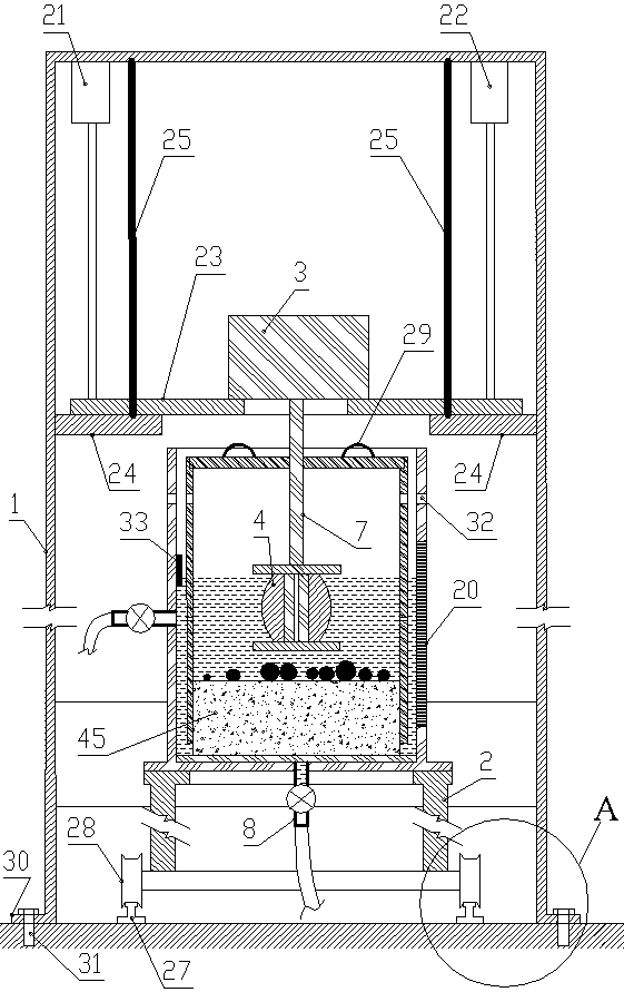
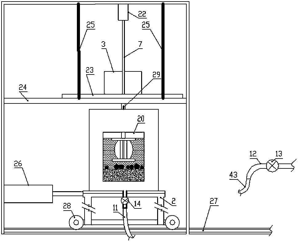
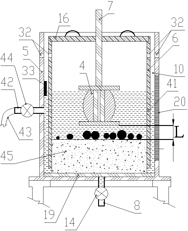
[0070] Such as Figure 1 to Figure 8 As shown, the concrete abrasion resistance test system of the present invention includes a concrete abrasion mechanism, a frame and a water inlet mechanism.

[0071] The frame includes an outer fixed frame 1 and an inner mobile frame 2.

[0072] The concrete grinding mechanism includes a stirring motor 3 arranged on the outer fixed frame 1 and a cylindrical body arranged on the inner moving frame 2, and the stirring paddle 4 is connected to the shaft of the stirring motor 3.

[0073] The cylinder body includes a steel outer cylinder body 5 and an inner cylinder body 6 made of wear-resistant plastic placed in the outer cylinder body 5. There is a gap 10 with a circular cross section between the outer cylinder body 5 and the inner cylinder body 6; the outer cylinder body 5 has a bottom plate (the outer cylinder body and the bottom plate are integrally set), and the inner cylinder body 6 is open up and down; specifically, the outer cylinder b...


PUM

PropertyMeasurementUnit
diameteraaaaaaaaaa
heightaaaaaaaaaa
thicknessaaaaaaaaaa

Abstract

The invention discloses a concrete abrasion resistance test system which comprises a concrete abrasion mechanism, a machine frame and a water inlet mechanism. The machine frame comprises an outer fixed machine frame body and an inner movable machine frame body. The concrete abrasion mechanism comprises a stirring motor and a cylinder. The cylinder comprises an outer cylinder body and an inner cylinder body. The water inlet mechanism comprises a water inlet pipe, a first hose and a first valve. A cylinder cover is arranged on the top of the inner cylinder body, and comprises two semicircular covers. Semicircular holes are correspondingly formed in the centers of the two semicircular covers and combined into a circular hole. A transparent inspection window is formed in the side wall of the outer cylinder body. The left side and the right side of the top of the outer fixed machine frame body are downwards connected with a first electric push rod and a second electric push rod respectively. The lower portion of the rear end of the outer fixed machine frame body is fixedly connected with a third electric push rod. The invention further discloses a concrete abrasion resistance test method using the concrete abrasion resistance test system. The test efficiency is improved, labor intensity is reduced, remote monitoring and control can be achieved, and good application and popularization value is achieved.

Description

technical field [0001] The invention relates to a test system, in particular to a concrete anti-scour test system for testing the anti-scour performance of concrete. Background technique [0002] In the field of hydraulic concrete engineering, it is necessary to test the wear resistance of concrete, that is, it is necessary to test the relative resistance of the concrete surface to the abrasion of high-speed flowing media, which is used to evaluate the relative abrasion resistance of the concrete surface. [0003] my country is a country with many sandy rivers. Among the many rivers, there are more than 60 rivers with a maximum annual sediment discharge of more than 10 million tons. Hydraulic structures on sediment-laden rivers are mostly concrete structures, and one of the main failure modes is material damage caused by erosion and abrasion of the flow surface due to high-speed sediment-laden water flow. [0004] The abrasive wear rate of concrete is a time-dependent state...

Claims


Application Information

Patent Timeline
Patent Type & Authority Patents(China)
IPC IPC(8): G01N3/56G01N5/04
CPCG01N3/567G01N5/04
Inventor 黄功学范伟丽高琴月黄振离陶新红王化民魏恒志姚广华白玉锋李骚冯逸君孙浩瑜梁振华李超
Owner 黄功学
Learn More