Supercharge Your Innovation With Domain-Expert AI Agents!

Magnetic conductive medium structure and stator disc and coreless disc-type motor having same

A technology of a magnetic conductive medium and a disc motor, applied in the field of mechanical motors, can solve the problems of increasing the length of the air gap of the motor, complicated manufacturing process, increasing the torque ripple of the motor, etc., so as to improve the magnetic field density of the air gap, reduce the manufacturing cost, The effect of reducing torque ripple

Inactive Publication Date: 2016-05-11
HUBEI HAISHAN TECH CO LTD
View PDF0 Cites 1 Cited by
  • Summary
  • Abstract
  • Description
  • Claims
  • Application Information

AI Technical Summary

Problems solved by technology

The existence of cogging brings cogging torque to the motor, which increases the torque ripple of the motor and greatly reduces the running effect of the motor
Based on the design of the magnetic circuit, the yoke of the tooth slot needs to provide a magnetic flux path, and the magnetic circuits on both sides of the intermediate stator structure must pass through the yoke. It is necessary to ensure a certain thickness, and at the same time add the thickness of the tooth itself, the thickness of the stator part is relatively large, resulting in a long axial length of the entire motor, which is not conducive to use in some occasions where the structure and installation requirements are compact
Due to the increase in thickness, enough air gap space is necessary to ensure the normal operation of the motor. In order to maintain the magnetic field strength within a certain range, the thickness of the permanent magnet of the rotor must be increased, which requires a large amount of magnetic steel, which greatly improves the manufacturing of the motor. cost
At the same time, the iron loss of the stator part is more, and the heat generation is more serious
The intermediate rotor often fixes the magnetic steel on the rotor bracket made of non-magnetic material. In the case of high speed and high power density, in order to ensure the safety of use, this structure is very difficult to package and batch production is very difficult.
[0004] The coreless structure is also called injection molding or pouring forming structure. This structure is a process of placing the wound coil in the mold and then injecting or pouring it into one body. The manufacturing process of the winding is complicated, and the stator disk made by this process is relatively Thick, resulting in an increase in the equivalent air gap length of the motor, resulting in a large excitation magnetic potential and a low utilization rate of magnetic field power density
Since the ironless structure removes the iron core material in the middle of the stator disk, compared with the iron core structure using the same permanent magnet material, the torque generated is smaller. If the same torque is to be achieved, the ironless structure needs to use more The permanent magnet material will inevitably increase the manufacturing cost of the motor
[0005] In summary, the main defects of the existing technology are: first, the existence of the cogging of the iron core structure brings the cogging torque to the motor, increases the torque ripple of the motor, and greatly reduces the operating effect of the motor; second , although the ironless structure has no cogging, in order to achieve the same torque as the iron core structure, the amount of permanent magnet material has to be increased, which greatly increases the manufacturing cost of the motor; third, the existing structure has very high requirements for packaging. High, the manufacturing process is complicated, and the batch production is very difficult; Fourth, the existing structure causes the axial length of the motor to be long, which is not conducive to the use of compact occasions

Method used


Image

  • Magnetic conductive medium structure and stator disc and coreless disc-type motor having same
  • Magnetic conductive medium structure and stator disc and coreless disc-type motor having same
  • Magnetic conductive medium structure and stator disc and coreless disc-type motor having same

Examples


Embodiment 1

[0042] Please refer to Figure 4A and Figure 4B , respectively, are the top view and the left partial enlarged view of the stator disk with the magnetic conductive medium structure provided in the embodiment of the present invention, and refer to Figure 4C and Figure 4D , respectively are the mechanical characteristic curve diagram and the motor efficiency curve diagram of the stator disk motor with the magnetic conductive medium structure provided in the embodiment of the present invention.

[0043] The stator disk (2) in this embodiment includes:

[0044] Axle hole (21);

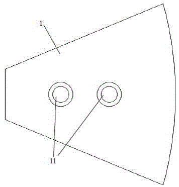
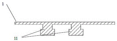
[0045] the substrate (22), in this embodiment, 12 pairs of mounting positions (24) are evenly arranged on the surface of the substrate (22) with a phase difference of 30 degrees, and the mounting positions (24) may be grooves or through holes;

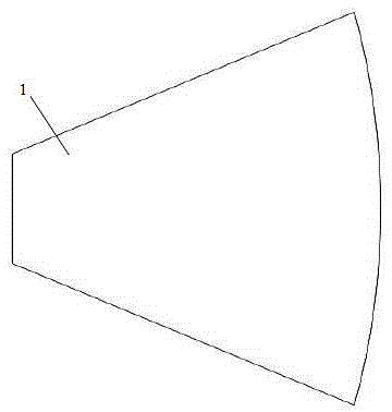
[0046] A magnetically conductive medium structure (1), in this embodiment, the magnetically conductive medium structure (1) is located on two surfaces of th...

Embodiment 2

[0053] Please refer to Figure 5A and Figure 5B , which are a top view and a left side view of the stator disk with the magnetic conductive medium structure provided in the embodiment of the present invention, respectively.

[0054] The stator disk described in this embodiment includes:

[0055] Axle hole (21);

[0056] substrate (22);

[0057] The magnetic conductive medium structure (1), in this embodiment, the magnetic conductive medium structure (1) is located on the same side of the substrate, the material is a soft magnetic composite material, and the shape is sector-shaped, and the mutually independent magnetic conductive medium structures (1) are The 30-degree phase difference is sequentially installed on the same side of the base plate (22) of the stator disc (2), and is pasted and fixed on the base plate by glue;

[0058] The coil winding (23), in this embodiment, the coil winding (23) adopts enameled round wire, the bare wire diameter is 0.55mm, each phase has ...

Embodiment 3

[0061] See Image 6 , which is a plan view of the stator disk with the magnetic conductive medium structure provided in the embodiment of the present invention.

[0062] The stator disk described in this embodiment includes:

[0063] Axle hole (21);

[0064] The base plate (22), in this embodiment, nine pairs of mounting positions are evenly arranged on the surface of the base plate with a phase difference of 40 degrees, and the mounting positions may be grooves or through holes;

[0065] A magnetic conductive medium structure (1), in this embodiment, the magnetic conductive medium structure (1) is located on the same side of the substrate (22), the material is a soft magnetic composite material, and the shape is sector-shaped, each of the magnetic conductive medium structure (1) ) with 2 protruding step-type fixed positions, the mutually independent magnetic conductive medium structures (1) are sequentially installed on the same side of the stator plate (2) base plate (22) ...


PUM


Abstract

The invention provides a magnetic conductive medium structure, which is used for a stator disc of a coreless disc-type motor. The stator disc comprises a substrate having a shaft hole and coil windings arranged on the substrate. The stator disc also comprises mutually-independent magnetic conductive medium structures, which are arranged on the substrate. The coil windings are arranged around the mutually-independent magnetic conductive medium structures. The invention provides the coreless disc-type motor embedded with the magnetic conductive medium structure. A non-cogging structure removes torque ripples of a core motor, so that operation effect of the motor is improved, axial length of the stator disc is reduced, the size of the motor is reduced, and the motor is allowed to be applied to more occasions; the magnetic conductive medium structure is added to enable the magnetic field intensity to be improved greatly; and under the condition of same torque, usage amount of the permanent magnet material can be reduced, and the manufacture cost of the motor is reduced.

Description

technical field [0001] The invention relates to the technical field of mechanical motors, in particular to a magnetically conductive medium structure, a stator disk and an ironless disk motor with the magnetically conductive medium structure. Background technique [0002] With the trend of miniaturization of electrical equipment, the demand for micro motors is increasing. Disc motors have many advantages such as small size, light weight, compact structure and high efficiency, and are widely used in various industrial equipment. In the prior art, most of the stator discs used for disc motors are of iron-core or ironless structure. According to the principle of electromagnetic induction, the phase current can generate a rotating magnetomotive force around the coil through the coil, so that the rotor of the permanent magnet presses The direction of the rotating magnetic field rotates to achieve the purpose of motor operation. [0003] The iron-core structure is mostly composed...

Claims


Application Information

Patent Timeline
Patent Type & Authority Applications(China)
IPC IPC(8): H02K23/54H02K23/58H02K1/17H02K3/46
CPCH02K23/54H02K1/17H02K3/46H02K23/58H02K2201/03
Inventor 周飞吴小青段建华
Owner HUBEI HAISHAN TECH CO LTD
Features
  • R&D
  • Intellectual Property
  • Life Sciences
  • Materials
  • Tech Scout
  • Unparalleled Data Quality
  • Higher Quality Content
  • 60% Fewer Hallucinations
Learn More