
Coal-to-oil catalytic extraction technology and special device thereof

A special device, coal-to-oil technology, applied in the petroleum industry, processing hydrocarbon oil, preparation of liquid hydrocarbon mixture, etc., can solve the problems of many auxiliary facilities, high cost of refined oil, large water consumption, etc., to avoid heat intensity Too high, reduce heating intensity, reduce the effect of heating intensity

Inactive Publication Date: 2016-05-25
金先奎 +1
View PDF7 Cites 4 Cited by
  • Summary
  • Abstract
  • Description
  • Claims
  • Application Information

AI Technical Summary

Problems solved by technology

[0042] (1) The technical process is long, there are many auxiliary supporting facilities, and some equipment is seriously worn; (2) The equipment is huge, the materials are expensive, the system is complicated, and the investment is high; (3) The water consumption is large; (4) The cost of refined oil is high; (5) The yield of refined oil is slightly lower; (6) The economic benefit is poor

Method used


Image

  • Coal-to-oil catalytic extraction technology and special device thereof

Examples


Embodiment 1

[0063] This embodiment provides a catalytic extraction coal-to-oil process, characterized in that: the catalytic extraction coal-to-oil process, the specific steps are:

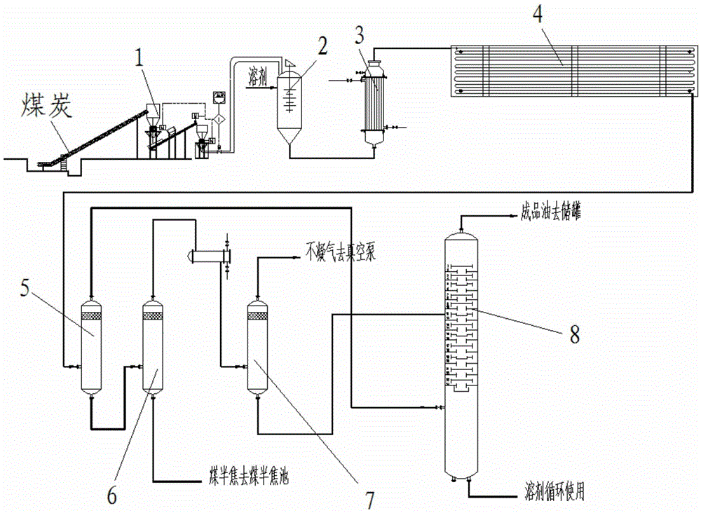
[0064] First, pulverize the coal to 180 mesh with a pulverizer. Coal is fully dissolved in the solvent, from solid powder form to coal solution form. The pulverized coal is sent to the pulverized coal tank by means of gas transportation. The pulverized coal enters the pulping tank from the bottom of the pulverized coal tank. The slurry tank is intermittently stirred, so that the pulverized coal and oil are fully mixed into a coal slurry state. The coal slurry enters the tube heater. The outlet temperature of the heater reaches 450°C and the pressure is 5MPA. The coal powder is completely dissolved in the solvent, and the pyrolysis reaction starts to take place. The coal slurry enters the pure axial flow reactor to become a coal solution. The coal solution is kept at 450°C and the pressure is 5MPA. The ...

Embodiment 2

[0075] This embodiment provides a catalytic extraction coal-to-oil process, characterized in that: the catalytic extraction coal-to-oil process, the specific steps are:

[0076] First, pulverize coal to 200 mesh with a pulverizer. Coal is fully dissolved in the solvent, from solid powder form to coal solution form. The pulverized coal is sent to the pulverized coal tank by means of gas transportation. The pulverized coal enters the pulping tank from the bottom of the pulverized coal tank. The slurry tank is intermittently stirred, so that the pulverized coal and oil are fully mixed into a coal slurry state. The coal slurry enters the tube heater. The outlet temperature of the heater reaches 480°C and the pressure is 8MPA. The coal powder is completely dissolved in the solvent, and the pyrolysis reaction starts to take place. The coal slurry enters the pure axial flow reactor to become a coal solution. The coal solution is kept at 480°C and the pressure is 8MPA. The resi...

Embodiment 3

[0087] This embodiment provides a catalytic extraction coal-to-oil process, characterized in that: the catalytic extraction coal-to-oil process, the specific steps are:

[0088] First, pulverize the coal to 220 mesh with a pulverizer. Coal is fully dissolved in the solvent, from solid powder form to coal solution form. The pulverized coal is sent to the pulverized coal tank by means of gas transportation. The pulverized coal enters the pulping tank from the bottom of the pulverized coal tank. The slurry tank is intermittently stirred, so that the pulverized coal and oil are fully mixed into a coal slurry state. The coal slurry enters the tube heater. The outlet temperature of the heater reaches 500°C and the pressure is 10MPA. The coal powder is completely dissolved in the solvent, and the pyrolysis reaction starts to take place. The coal slurry enters the pure axial flow reactor to become a coal solution. The coal solution is kept at 500°C and the pressure is 10MPA. Th...


PUM


Abstract

The invention relates to a coal-to-oil catalytic extraction technology. The technology concretely comprises the steps of firstly, pulverizing coal by a pulverizer, and enabling the pulverized coal to enter a slurry preparation tank; enabling the slurry preparation tank to stir in an intermittent way, and enabling the pulverized coal and oil to be fully mixed together to form a coal slurry state; enabling the coal slurry to enter a tubular heater; reducing the pressure of the reaction product coming out from a pure axial flow reactor, then enabling the reaction product to enter a high-pressure separating tank, and carrying out flash evaporation on the reaction product; enabling light oil constituent coming out from the top of the high-pressure separating tank to enter the bottom of a rectifying tower in the form of gas phase; enabling the reaction product at the bottom of the high-pressure separating tank to enter a low-pressure separating tank; enabling product oil to come out from the top of the rectifying tower, and enabling a solvent to come out from the bottom of the rectifying tower; cooling the product oil, then enabling the cooled product oil to enter a storage tank and enabling the solvent to enter a solvent tank for recycling. The invention also provides a special device of the coal-to-oil catalytic extraction technology. The device comprises the pulverizer, the slurry preparation tank, the heater, the reactor, the high-pressure separating tank, the low-pressure separating tank, a vacuum tank and a solvent recovery tower; all the modules are sequentially connected. The coal-to-oil catalytic extraction technology and the special device of the coal-to-oil catalytic extraction technology have the advantages that the production technology is simplified, the equipment efficiency is improved, the energy consumption of production is reduced, the pollution is reduced, the raw material utilization rate is improved, and the production cost per ton of oil is lowered.

Description

technical field [0001] The invention relates to the field of catalytic extraction of coal to oil, in particular to a process of catalytic extraction of coal to oil and a special device thereof. Background technique [0002] First of all, catalytic extraction of coal to oil requires hydrogenation to remove oxygen, sulfur, nitrogen and heavy metal gas oil. Containing aromatics such as naphthalene and phenol, it is a substitute for petroleum. As a resource that can replace petroleum, coal-to-oil is highly valued by the state. With the intensification of the contradiction between international and domestic oil supply and demand, it has become the consensus of all walks of life to speed up the development of coal-to-oil technology, and the coal-to-oil industry has developed rapidly. At present, my country's dependence on foreign oil has reached more than 60%, and the security of energy strategy is very fragile; and coal resources are abundant, and the proven reserves can be expl...

Claims


Application Information

Patent Timeline
IPC IPC(8): C10G1/04C10G1/00
CPCC10G1/04C10G1/002C10G1/083C10G2300/10
Inventor 金先奎林秀惠
Owner 金先奎
Learn More