Blowing-type induction melting furnace

An induction melting furnace and injection technology, which is applied in the field of metallurgy, can solve the problem that induction heating cannot be applied, and achieve the effects of intensified purification and impurity removal, less difficulty in operation and low cost.

Inactive Publication Date: 2016-05-25
NORTHEASTERN UNIV
View PDF7 Cites 5 Cited by
  • Summary
  • Abstract
  • Description
  • Claims
  • Application Information

AI Technical Summary

Problems solved by technology

However, if the presence of carbon is strictly limited for the h

Method used


Image

  • Blowing-type induction melting furnace
  • Blowing-type induction melting furnace

Examples


Example Embodiment

[0021] Example 1

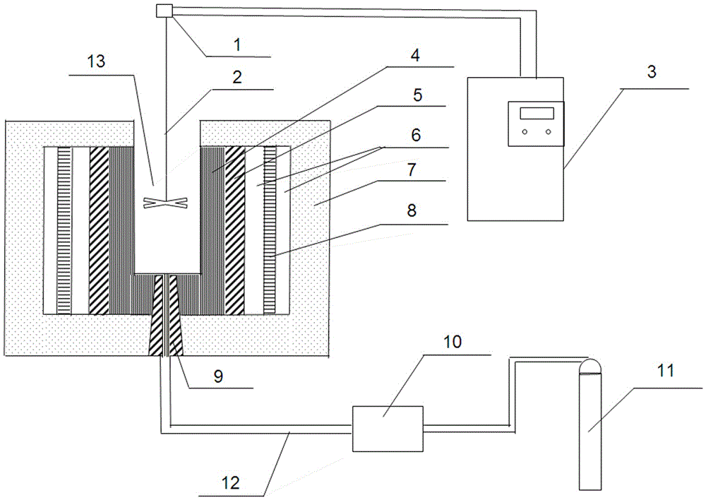
[0022] A blown induction melting furnace, such as figure 1 As shown, it includes a furnace body 7, a slit-type ventilation brick 9, a mechanical stirring system, a storage tank 10, a gas source 11, a high-pressure carrier gas delivery pipeline 12, and an induction system; wherein the furnace body 7 has an upper opening, and the inner wall and the induction system The refractory crucibles 4 are separated and sealed by insulating materials; the stirring paddle 2 of the mechanical stirring system is inserted into the molten pool 13 formed by the furnace body 7 and the refractory crucibles 4, and the rotating speed during operation is controlled by the control box 3. The box 3 is connected to the stirring head 1 of the stirring paddle 2; the storage tank 10 is located between the gas source 11 and the furnace body 7, and is connected to each other through a high-pressure carrier gas delivery pipeline 12, which is connected to the furnace body 7 The air outlet i...

Example Embodiment

[0025] Example 2

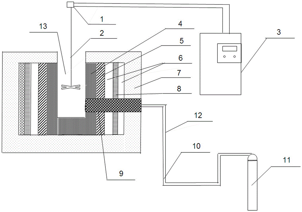
[0026] A blown induction melting furnace, such as figure 2 As shown, the structure of the induction melting furnace is the same as that of Example 1, the difference is that: the ventilation brick 9 is a diffuse type ventilation switch, which is arranged on the side wall of the furnace body 7, and the electromagnetic induction body is selected from lanthanum hexaboride, and the induction melting furnace structure does not have Storage tank 10.

[0027] Utilize the injection type induction smelting furnace of this embodiment to carry out copper slag depletion treatment, the process is as follows: join molten copper slag in the melting pool, start induction heating system to keep material temperature at 1150 ~ 1350 ℃; Insert it into 1 / 3~1 / 2 of the melt height in an eccentric manner, start mechanical stirring; at the same time, open the high-pressure carrier gas source of the injection system, inject reducing gas for reduction smelting, and remove iron, copper...


PUM


Abstract

The invention provides a blowing-type induction melting furnace which comprises a furnace body, an air brick, a mechanical stirring system, a blowing system and an induction system, wherein the furnace body and a refractory crucible of the induction system form a molten pool; the inner wall of the furnace body and the induction system are partitioned and sealed through a thermal insulation material; the air brick is arranged at the bottom part or the side wall of the furnace body, directly passes through the furnace body and is communicated with the induction system and the molten pool; the mechanical stirring system comprises a mixing propeller and a control box; the mixing propeller is inserted into the molten pool and controls the rotating speed when working through the control box; the blowing system comprises a gas source and a high-pressure carrier gas transmission pipeline, and is connected with the bottom part of the furnace body through the high-pressure carrier gas transmission pipeline; an air outlet of the pipeline is opposite to the air brick; the induction system comprises an induction coil, an electromagnetic induction body, the refractory crucible and the thermal insulation material; the induction coil is in tight contact with the thermal insulation material on the inner wall of the furnace body; the thermal insulation material is arranged between the induction coil and the electromagnetic induction body; and the refractory crucible is located on the innermost layer.

Description

technical field [0001] The invention belongs to the technical field of metallurgy, and in particular relates to a jet-type induction melting furnace. Background technique [0002] With the improvement of pyrometallurgy copper smelting intensity and copper matte grade, the copper content in copper slag is as high as 0.4%-0.8%, and the copper content in copper slag in oxygen-enriched blowing process is even as high as 3-4% (much higher than 0.3 % copper mining grade). There are two types of copper slag dilution methods in industry: slow cooling and beneficiation and pyrolysis. The slow cooling mineral processing method can only recover most of the inclusion matte, and the copper content in the mineral processing tailings is less than 0.35%, but the valuable components such as iron in the copper slag cannot be recycled. The fire depletion method is to add a vulcanizing agent to the molten copper slag for depletion treatment, and the copper-sulfur phase is recovered through se...

Claims


Application Information

Patent Timeline
IPC IPC(8): C22B15/00C22B7/04
CPCC22B15/003C22B15/0054Y02P10/20
Inventor 张廷安豆志河牛丽萍刘燕张保敬吕国志张子木赵秋月
Owner NORTHEASTERN UNIV
Why Eureka
Try Eureka