
Electrochemical thin-film condensation sensor

A condensation sensor, electrochemical technology, applied in the field of sensors, can solve the problems of unquantifiable surface condensation, complex structure, complex operation, etc., and achieve the effect of strong practicability, simple structure, and good response

Inactive Publication Date: 2016-05-25
HUAIBEI POWER SUPPLY COMPANY OF STATE GRID ANHUI ELECTRIC POWER +1
View PDF6 Cites 7 Cited by
  • Summary
  • Abstract
  • Description
  • Claims
  • Application Information

AI Technical Summary

Problems solved by technology

Due to the existence of an optical path system in the optical condensation sensor, the structure is complex, and liquid nitrogen or dry ice is generally used as a cold source. Therefore, a corresponding evaporator is required, which is not only large in size, complicated in operation, but also difficult to precisely control the temperature.
The capacitive condensation sensor can be completed with a high-precision capacitance measurement chip to achieve miniaturization, but the moisture absorption and condensation of the dielectric and the delay in the drying process interfere with the dynamic characteristics of the condensation measurement; moreover, the amount of water condensation on the surface during the condensation process cannot Quantify
[0003] The condensation sensor cannot accurately measure surface condensation and quantify the amount of condensation, which often makes it difficult to effectively implement protection measures for equipment and facilities that are sensitive to condensation.
For example, power switching equipment is usually arranged in a semi-closed metal cabinet, and the temperature difference between the inside and outside is likely to cause condensation on the surface of the switch contact, which affects the safety of the switch and the life of the equipment; traditional condensation monitoring technology often has water droplets in the cabinet It has not been detected yet, resulting in the abnormal opening of the condensation controller

Method used


Image

  • Electrochemical thin-film condensation sensor
  • Electrochemical thin-film condensation sensor
  • Electrochemical thin-film condensation sensor

Examples


Embodiment Construction

[0030] The present invention will be further described below in conjunction with the accompanying drawings.

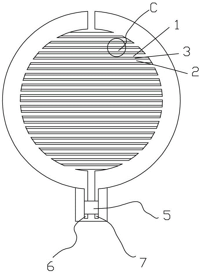
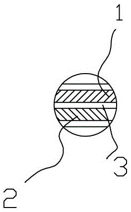
[0031] Such as figure 1 As shown, the present invention has a comb-like structure, and the positive electrode 1 and the negative electrode 2 are arranged alternately in a comb-like shape. The smaller the gap between the positive electrode conductor material and the negative electrode conductor material, the better the sensitivity to condensation, but due to the limitation of material processing technology, combined with image 3 As shown, the distance between the positive electrode 1 and the negative electrode 2 is set at 0.01-1 mm. The positive electrode 1 and the negative electrode 2 are connected to the output positive electrode 6 and the output negative electrode 7 through the amplifier circuit 5 . The positive electrode 1 and the negative electrode 2 are output to the amplifying circuit 5 , and the amplified signal is output by the sensor through the positive ou...


PUM

PropertyMeasurementUnit
Diameteraaaaaaaaaa

Abstract

The present invention discloses an electrochemical thin-film condensation sensor, and solve the problem that a conventional device can not accurately measure surface condensation. The sensor is characterized by comprising a positive electrode, a negative electrode, an insulating layer, an amplifier circuit, an output positive electrode and an output negative output. The positive electrode and negative electrode are disposed on the same side or the opposite sides of the insulating layer; the insulating layer is a substrate for the positive electrode and the negative electrode; the positive electrode and the negative electrode are connected to the output positive electrode and output negative electrode by the amplifier circuit. The sensor uses conductor materials with different potential ordinals to form heterogeneous electrode pair, forms an original battery after surface condensation, and has a Faraday current output. The sensor is simple in structure and convenient for surface mounting in key parts of condensation sensitive equipment and facilities, has good response to the state of condensation, and realizes the monitoring on the amount of surface condensation.

Description

technical field [0001] The invention belongs to the technical field of sensors, and more specifically relates to a condensation sensor. Background technique [0002] Currently, there are two types of condensation sensors: (1) capacitive condensation sensors; (2) optical condensation sensors. The measurement principle of the capacitive condensation sensor is the electrical principle. The effective dielectric constant of the dielectric layer changes before and after "condensation", and the capacitance varies greatly. The chip is used to measure the capacitance change of the capacitor to measure the condensation state of the surface. The common optical condensation sensor is the cold mirror condensation sensor, which is based on the optical principle. After "condensation", the reflection ability of the mirror to light is significantly weakened, and the surface condensation is detected by detecting the change of the reflected light. Due to the optical path system of the optical...

Claims


Application Information

Patent Timeline
IPC IPC(8): G01N27/26G01N27/416
CPCG01N27/26G01N27/416
Inventor 杨光辉陈强孙丹彤张建民唐健张先云
Owner HUAIBEI POWER SUPPLY COMPANY OF STATE GRID ANHUI ELECTRIC POWER
Learn More