A swirl coupling deep desulfurization strengthening module

A deep desulfurization, swirling plate technology, applied in chemical instruments and methods, using liquid separating agents, gas treatment, etc., can solve the problems of large flow rate through the plate, increased flue gas resistance, low opening rate, etc. Liquid mass transfer rate, improving gas-liquid contact time, preventing scaling or clogging

Active Publication Date: 2018-06-29
SHANGHAI JIAO TONG UNIV
View PDF11 Cites 0 Cited by
  • Summary
  • Abstract
  • Description
  • Claims
  • Application Information

AI Technical Summary

Problems solved by technology

Although the technical solution disclosed in this patent has a simple structure and high desulfurization efficiency, it is hoped that the upper spraying layer will be sprayed because two simplified swirl plates are simply connected in series to form an assembly and placed on the tray at the bottom of the spray layer. The desulfurization liquid that is poured down is used for secondary utilization to improve the desulfurization efficiency, which has the following disadvantages: 1) A cylindrical series swirl unit is installed on the bottom tray, and the flue gas passes through each unit due to its low porosity. The flow velocity through the plate of the first swirl element is too large, resulting in a large resistance (in actual use, only the resistance of this layer of the tray can reach more than 1000Pa), which seriously deviates from the "energy-saving" design requirements; 2) the two-layer swirl plate It is unreasonable to use it in series for absorption desulfurization, because if the desulfurization liquid from top to bottom is spilled on the periphery of the swirl plate cylinder, it cannot be used by the upper swirl plate, even if it is sprayed on the upper swirl plate The desulfurization liquid on the blade, through the centrifugal injection of the plate, almost all flows down along the periphery of the cylinder, which cannot realize the real "convergence" effect, thus causing the desulfurization liquid coming down from the upper layer to fail to reach the central blind of the lower swirl plate. The plate area is used for secondary swirl injection (the desulfurization liquid can only be effectively used if it is distributed on the blind plate area or on the blades near the blind plate), resulting in most of the lower swirl plates being in a "dry plate" state, which cannot achieve the desired effect. 3) Although the conical constriction can be used to introduce part of the desulfurization liquid to the blades of the lower swirl plate, the constriction will further increase the flue gas resistance, which limits its practicability

Method used


Image

  • A swirl coupling deep desulfurization strengthening module
  • A swirl coupling deep desulfurization strengthening module
  • A swirl coupling deep desulfurization strengthening module

Examples


Embodiment 1

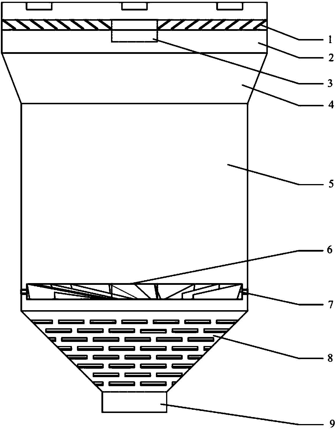
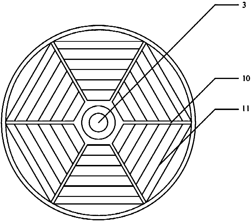
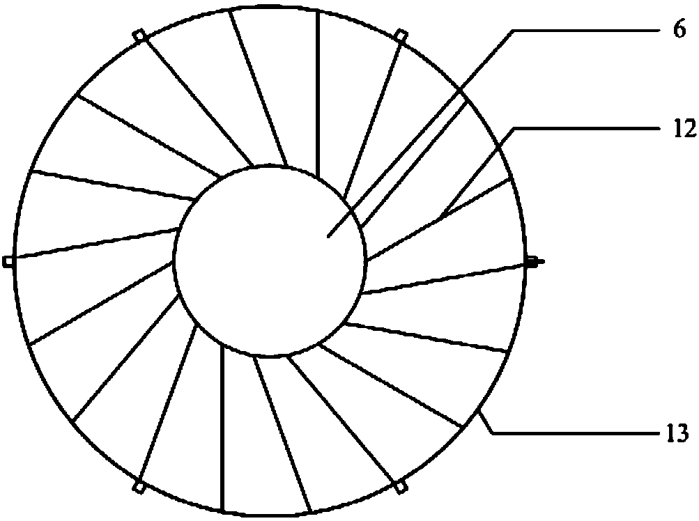
[0041] Such as figure 1 As shown, a swirl coupled deep desulfurization module is arranged at the lower part of the spray layer of the desulfurization tower, including an outer cylinder with open upper and lower ends and a slit cone arranged in the outer cylinder from bottom to top. Bottom cover 8, outward jet swirl plate 7 and inward jet manifold 1, the side wall of slit conical bottom cover 8 is provided with the slit mouth 14 that passes through for air flow, and the center of outward jet swirl plate 7 is provided with blind plate 6, the center of the inward jetting manifold 1 is provided with a downcomer 3 that guides the desulfurization liquid to the blind plate 6, and the bottom of the slit conical bottom cover 8 is also provided with a conical bottom cover downcomer 9; In this state, the desulfurization liquid sprayed from the spray layer onto the inward jet manifold 1 is sprayed centripetally, and the desulfurization liquid converges to the center of the inward jet mani...

Embodiment 2

[0054] In this embodiment, the elevation angle between the inward blades 11 in the inward jet manifold 1 and the horizontal plane is 28°, the aperture ratio is 30%, and the elevation angle between the jet blades in the outward jet swirl plate 7 and the horizontal plane is 30°. The porosity is 35%. All the other are with embodiment 1.

[0055] For a coal-fired boiler with an evaporation capacity of 30t / h, the designed flue gas volume is 85,000m 3 / h, the flue gas temperature is 150°C, and the sulfur dioxide concentration in the inlet flue gas reaches 3500mg / Nm 3 . The module of this embodiment is added, the inner diameter of the desulfurization tower is 2500 mm, and the flue gas desulfurization process of limestone-gypsum method is adopted. When the boiler load is 90%, the liquid-gas ratio is 1.8L / m 3 The measured desulfurization efficiency is 99.5% (the concentration of sulfur dioxide in the outlet flue gas is lower than 30mg / Nm 3 ), the airflow resistance of the whole to...

Embodiment 3

[0057] In this embodiment, the outer cylinder is composed of an upper cylinder 2 with a regular octagonal cross-section, a cylindrical lower cylinder 5, and a transition pipe 4 arranged between the upper cylinder 2 and the cylindrical lower cylinder 5, wherein, The diameter of the circumscribed circle of the regular octagon is 1500mm.

[0058] In the inward jet manifold 1, there are 56 inward blades 11 in total, which are divided into 7 layers obliquely in the form of a regular octagon. The elevation angle between the inward blades 11 and the horizontal plane is 40°, and the width is 120mm. The width is 120mm.

[0059] The plurality of injection blades 12 in the outward injection swirl plate 7 are fan-shaped and obliquely fixed one by one, and the line between the center of the injection blade 12 and the center of the circle of the second support rib 13 is 60° with the injection blade 12. And the elevation angle between the spray blade 12 and the horizontal plane is 40°. The...


PUM

PropertyMeasurementUnit
angleaaaaaaaaaa
widthaaaaaaaaaa
angleaaaaaaaaaa

Abstract

The invention relates to a novel rotational flow coupling deep desulfurization intensifying module which is arranged at the lower part of a spraying layer of a desulfurizer and comprises an outer barrel, a slit conical bottom cover, an outward ejection rotational flow plate and an inward ejection confluence plate, wherein the upper and lower ends of the outer barrel are opened; the slit conical bottom cover, the outward ejection rotational flow plate and the inward ejection confluence plate are arranged in sequence from bottom to top; a slit hole through which air flows is formed in a side wall of the slit conical bottom cover; a blind plate is arranged in the center of the outward ejection rotational flow plate; a downcomer for leading a doctor solution into the blind plate is arranged in the center of the inward ejection confluence plate. Compared with the prior art, the novel rotational flow coupling deep desulfurization intensifying module is simple and compact in overall structure, desulfuration synergism can be achieved on premise that the height of the desulfurizer is not increased, the spraying layer of the desulfurizer is not increased and the liquid-gas ratio of the desulfurizer is not increased, under the condition that the slurry circulation volume is not changed, the energy consumption can be reduced, the ultralow emission requirement of sulfur can be met, the operation cost can be lowered, and good application prospects can be achieved.

Description

technical field [0001] The invention belongs to the technical field of environmental protection, and relates to a deep desulfurization strengthening module with swirl flow coupling, which is mainly used to be installed on the chassis position of the spray layer of a desulfurization tower to enhance the desulfurization effect of the spray tower. Background technique [0002] The ultra-low emission of flue gas from coal-fired power plants and large industrial boilers in my country will gradually become popular. However, the current enhanced desulfurization methods that can meet the ultra-low emission requirements are relatively extensive, especially the heightening of desulfurization towers or the use of double desulfurization towers to achieve ultra-low emission of sulfur dioxide. The low-emission method will lead to a sharp increase in the investment cost of desulfurization and dust removal equipment transformation, and an increase in operating costs. Therefore, it is urgent ...

Claims


Application Information

Patent Timeline
Patent Type & Authority Patents(China)
IPC IPC(8): B01D53/78B01D53/50B01D47/06
CPCB01D47/06B01D53/50B01D53/78B01D2258/0283
Inventor 晏乃强瞿赞朱雯斐黄文君张其龙赵松建徐浩淼谭天恩
Owner SHANGHAI JIAO TONG UNIV
Why Eureka
Try Eureka