Production assisting robot for numerical control machine tool
A technology of CNC machine tools and robots, applied in the directions of manipulators, metal processing, chucks, etc., can solve the problems of high price, short service life of mechanical fingers, complex structure, etc., and achieve the effect of reducing the floor space.
- Summary
- Abstract
- Description
- Claims
- Application Information
AI Technical Summary
Problems solved by technology
Method used
Image

Examples
Embodiment Construction
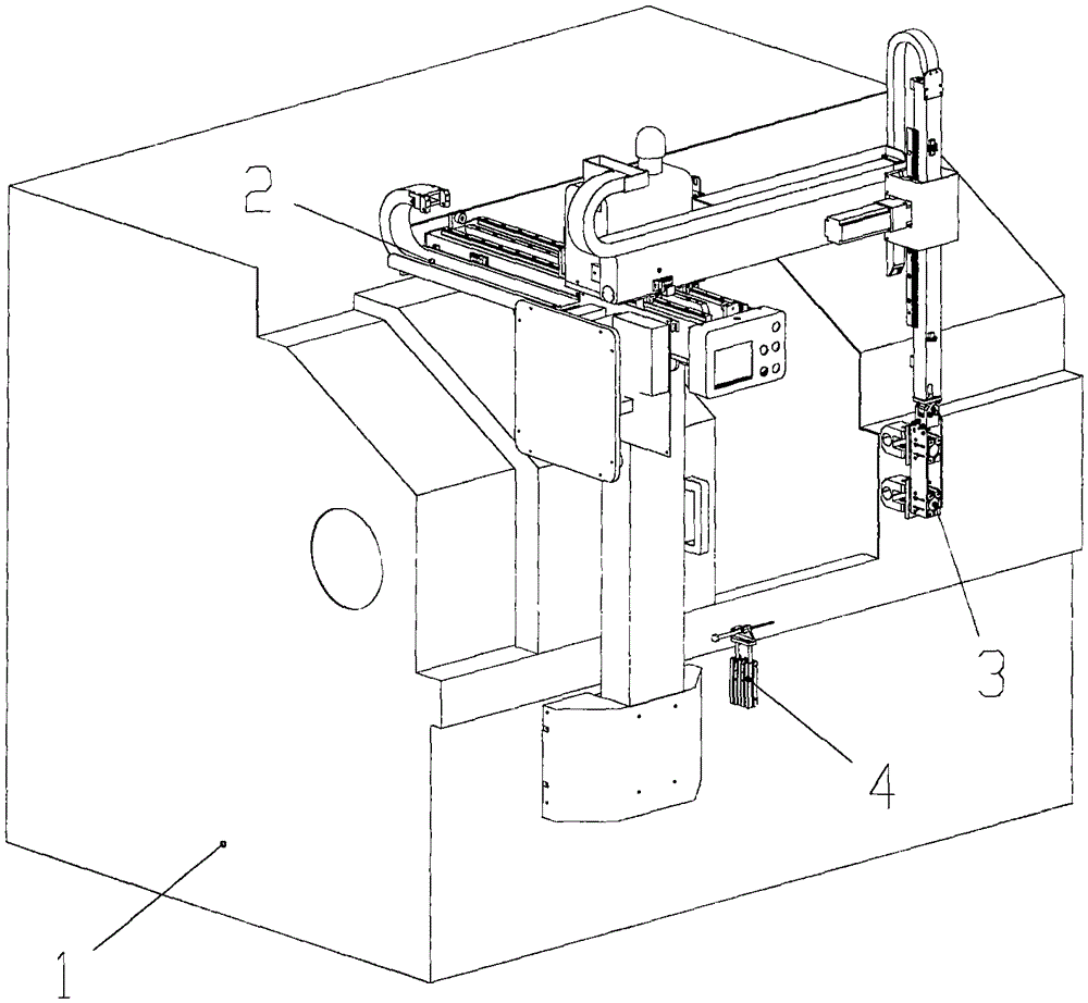
[0030] The present invention will be further described in detail below in conjunction with the accompanying drawings, but does not constitute any limitation to the present invention. Similar component numbers in the accompanying drawings represent similar components. As mentioned above, the present invention provides a CNC machine tool assisting production robot for grasping and transferring materials, combined with a CNC lathe, to realize automatic turning operations of the CNC lathe.
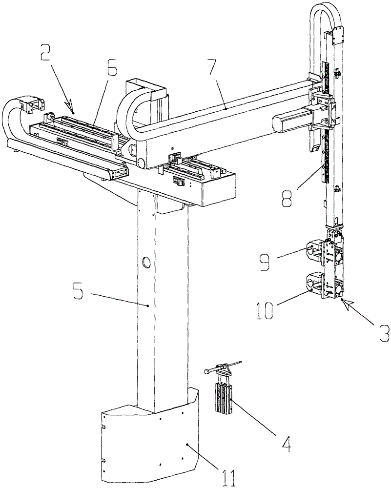
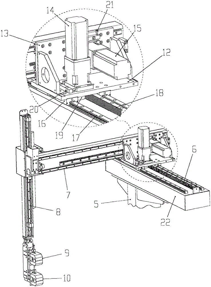
[0031] figure 1 It is a structural schematic diagram of the CNC machine tool assisting the production robot installed on the CNC lathe of the present invention, figure 2 , 3 It is a structural schematic diagram of the NC machine tool assisting the production robot of the present invention, Figure 4 It is a structural schematic diagram of the main part assembly of the X-axis sliding table of the CNC machine tool assisting in the production of the robot of the present invention, Figure 5 I...
PUM
 Abstract
Description
Claims
Application Information
 - Generate Ideas
- Intellectual Property
- Life Sciences
- Materials
- Tech Scout
- Unparalleled Data Quality
- Higher Quality Content
- 60% Fewer Hallucinations
Browse by: Latest US Patents, China's latest patents, Technical Efficacy Thesaurus, Application Domain, Technology Topic, Popular Technical Reports.
© 2025 PatSnap. All rights reserved.Legal|Privacy policy|Modern Slavery Act Transparency Statement|Sitemap|About US| Contact US: help@patsnap.com