Electrical fire cause analysis system and method
An analysis method and cause technology, applied in the field of smart home, can solve the problems of low current intensity, strong fire concealment, and lack of effective protection, and achieve the effect of improving electricity safety.
- Summary
- Abstract
- Description
- Claims
- Application Information
AI Technical Summary
Problems solved by technology
Method used
Image

Examples
Embodiment 1
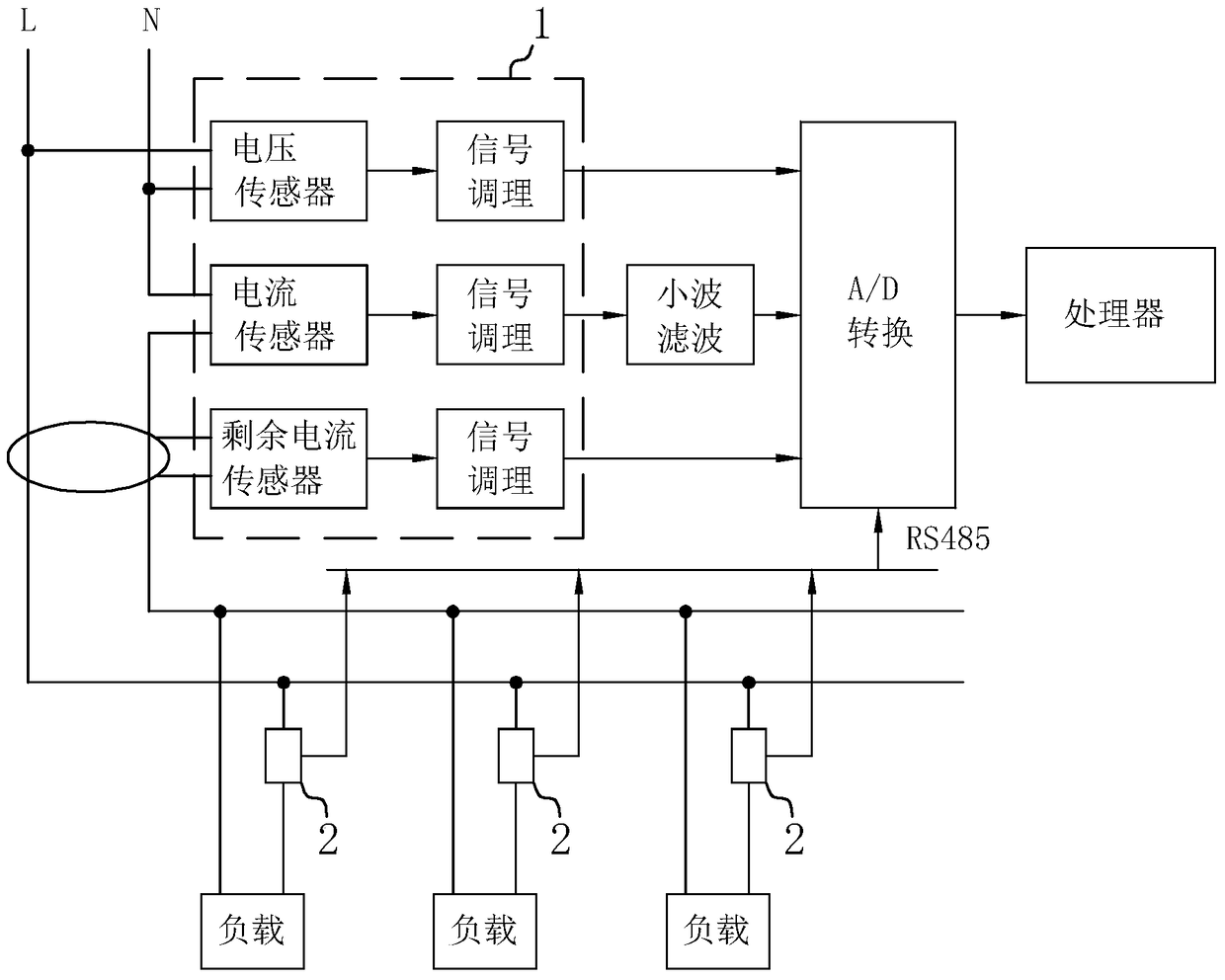
[0047] Such as figure 1, a circuit schematic diagram of a fire cause analysis system, in which the electrical fire cause analysis of the power grid taking the mains as an example is schematically illustrated, and the main road signal acquisition module 1 includes a voltage sensor, a current sensor and a residual current sensor, which are used to detect the power grid The current / voltage of the main circuit, the signals collected by the voltage sensor, current sensor and residual current sensor are transmitted to the A / D conversion module and then to the processor through the signal conditioning module, and the signal conditioning module of the current sensor is connected with the A / D A wavelet filter is also connected between the conversion modules to filter out white noise and impulse noise, eliminate burrs and small protrusions in the current waveform, make the waveform smoother, but maintain the signal characteristics of the fault arc, the processor The phase, frequency, ph...
Embodiment 2
[0058] Please refer to Figure 5 , the difference between Embodiment 2 and Embodiment 1 is that the calculation method of the matching degree P is: take the current value of the ideal current waveform preset phase α as the ideal value I 1 , α is not the current zero-crossing point, take the current value of the same preset phase α of the load current waveform as the actual value I 2 , the preset phase α is 15° before / after the zero crossing point, and the matching degree P=I 2 / I 1 , because the current is extinguished before the zero crossing point and re-ignites after the zero crossing point, the existence of the flat shoulder area makes the preset phase α different, if I 2 Sampling in the flat shoulder area, then P will approach 0, if I 2 If the sampling is outside the flat shoulder area, then P tends to 1.
Embodiment 3
[0060] A fire cause analysis method,
[0061] Collect the current waveform of the main road in real time through the main road signal acquisition module 1, and extract the electrical parameters of the main road including at least the phase and frequency of the main road current;
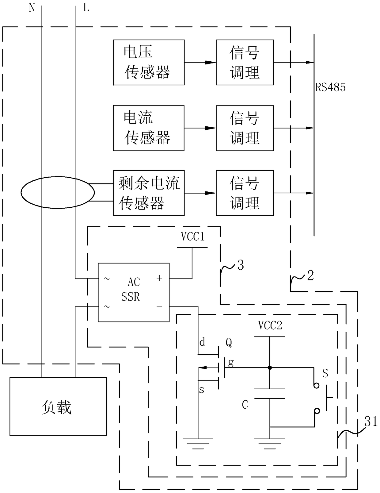
[0062] By independently configuring the branch signal acquisition module 2 in each branch used to connect the load to collect the load current waveform in real time, extract the branch electric parameters at least including the effective value of the load current of each branch, and at the same time in each branch The branches connected to the load are all connected in series with the time-delay non-contact switch module 3, which is used to reduce the good arc interference generated during plugging.
[0063] generating ideal current waveforms respectively corresponding to the loads of each branch according to the effective value of the main circuit electric parameter and the load current in each bran...
PUM
 Abstract
Description
Claims
Application Information
 - R&D
- Intellectual Property
- Life Sciences
- Materials
- Tech Scout
- Unparalleled Data Quality
- Higher Quality Content
- 60% Fewer Hallucinations
Browse by: Latest US Patents, China's latest patents, Technical Efficacy Thesaurus, Application Domain, Technology Topic, Popular Technical Reports.
© 2025 PatSnap. All rights reserved.Legal|Privacy policy|Modern Slavery Act Transparency Statement|Sitemap|About US| Contact US: help@patsnap.com