
Dilution treatment method for copper smelting slag

A technology of copper smelting slag and treatment method, which is applied in the field of metallurgy, can solve the problems of serious volatilization, serious environmental pollution, and low utilization rate, and achieve the effects of reducing copper content, reducing environmental pollution, and improving kinetic conditions

Inactive Publication Date: 2016-06-15
NORTHEASTERN UNIV
View PDF6 Cites 18 Cited by
  • Summary
  • Abstract
  • Description
  • Claims
  • Application Information

AI Technical Summary

Problems solved by technology

However, in the pyro-process depletion process, the vulcanizing agent is generally added directly at the top of the depleting furnace, and the vulcanizing agent floats on the surface of the slag, and the contact with the copper smelting slag is insufficient and volatilizes seriously, the utilization rate is low, and it is easy to cause environmental pollution
[0005] The patent application number is 200910088879.9 proposes an electrothermal depletion process for copper smelting slag, adding vulcanizing agent and copper smelting slag to the electrothermal depletion furnace, increasing the temperature of copper smelting slag by electrifying the electrodes, and spraying into the bottom of the depletion furnace at the same time Oxygen, and / or carbon monoxide gas and nitrogen gas mixture to improve copper recovery and resource utilization, but this patent does not consider the full mixing and reaction of vulcanizing agent and copper smelting slag, the utilization efficiency of vulcanizing agent is low, and due to the A large amount of sulfur dioxide gas is generated during the addition process, causing serious environmental pollution

Method used


Image

  • Dilution treatment method for copper smelting slag

Examples


Embodiment 1

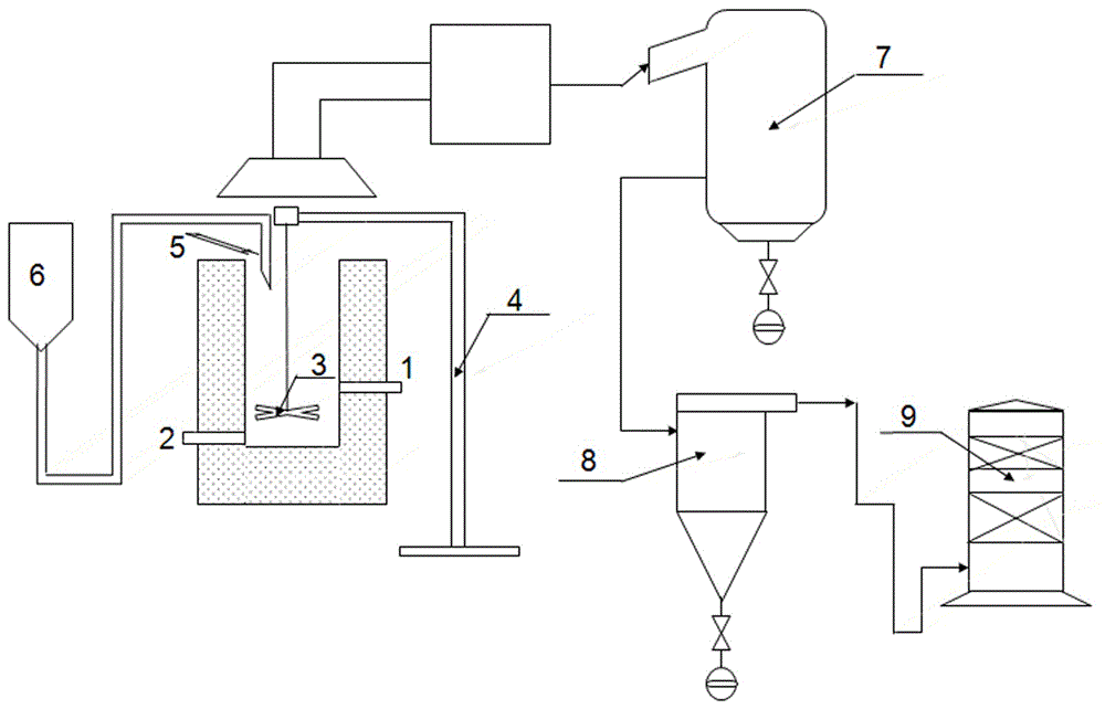
[0032] The amount of molten copper smelting slag is 20t, the composition is shown in Table 1, and the depletion furnace used is as follows figure 1 As shown, the depletion treatment method is carried out according to the following process steps:

[0033] (1) Introduce mechanical stirring equipment into the depletion furnace, introduce high-temperature molten copper smelting slag at 1150~1350 °C, adjust the stirring blade to extend to 1 / 3 of the liquid level of copper smelting slag, start heating and stirring, Control the temperature of copper smelting slag to 1250°C, the stirring speed to 50r / min, and form a vortex with a ratio of diameter to height of 3;

[0034] (2) Blow 600kg of copper concentrate and 400kg of calcium oxide from the nozzle above the high-temperature molten copper smelting slag liquid surface to the surface of the copper smelting slag pool near the center of the vortex, and keep stirring for 40 minutes;

[0035] (3) Static stratification, respectively colle...

Embodiment 2

[0038] The amount of molten copper smelting slag is 22t, and the composition is shown in Table 1. The depletion furnace used is as follows figure 1 As shown, the depletion treatment method is carried out according to the following process steps:

[0039] (1) Introduce mechanical stirring equipment into the depletion furnace, introduce high-temperature molten copper smelting slag at 1150~1350 °C, adjust the stirring blade to extend to 1 / 2 of the liquid level of copper smelting slag, start heating and stirring, Control the temperature of the copper smelting slag to 1280°C, the stirring speed to 200r / min, and form a vortex with a diameter-to-height ratio of 0.5;

[0040] (2) Blow 660kg of pyrite and 440kg of calcium oxide from the nozzle above the liquid surface of the high-temperature molten copper smelting slag to the surface of the copper smelting slag pool near the center of the vortex, and keep stirring for 60 minutes;

[0041] (3) Static layering, respectively collecting t...

Embodiment 3

[0044] The amount of molten copper smelting slag is 1 ton, and the composition is shown in Table 2. The depletion furnace used is as follows figure 1 As shown, the depletion treatment method is carried out according to the following process steps:

[0045] (1) Introduce mechanical stirring equipment into the depletion furnace, introduce high-temperature molten copper smelting slag at 1150~1350 °C, adjust the stirring blade to extend to 1 / 2 of the liquid level of copper smelting slag, start heating and stirring, Control the temperature of copper smelting slag to 1260°C, the stirring speed to 80r / min, and form a vortex with a ratio of diameter to height of 2;

[0046] (2) Blow 17kg of pyrite and 15kg of calcium oxide from the nozzle above the high-temperature molten copper smelting slag liquid surface to the surface of the copper smelting slag pool near the center of the vortex, and keep stirring for 30 minutes;

[0047] (3) Static layering, respectively collecting the lower laye...


PUM


Abstract

The invention provides a dilution treatment method for copper smelting slag. The dilution treatment method includes the technological steps that firstly, a mechanical stirring device is introduced into a dilution furnace, the high-temperature molten state copper smelting slag at the temperature ranging from 1150 DEG C to 1350 DEG C is guided into the dilution furnace, a stirring paddle is adjusted to stretch to the part from the 1 / 3 position of the liquid level of the copper smelting slag to the 1 / 2 position of the liquid level of the copper smelting slag, heating and stirring are started, the temperature of the copper smelting slag is controlled to range from 1200 DEG C to 1350 DEG C, the stirring speed ranges from 50 r / min to 200 r / min, and a vortex with the diameter height ratio ranging from 0.5 to 3 is formed; secondly, a vulcanizing agent is carried through carrier gas and injected to the position, close to the center of the vortex, of the surface of a copper smelting slag pool through a nozzle above the liquid level of the high-temperature molten state copper smelting slag, the adding amount of the vulcanizing agent is 0.3-8% of the mass of the copper smelting slag, and heat-preservation stirring is conducted for 10-60 min; and thirdly, standing layering is conducted, and copper matte on the lower layer and diluted slag on the upper layer are collected. The copper content of the diluted slag obtained after treatment is below 0.3%.

Description

technical field [0001] The invention belongs to the technical field of metallurgy, and in particular relates to a method for depleting copper smelting slag. Background technique [0002] Various copper smelting technologies have their own characteristics, and satisfy the modern copper smelting industry's energy efficiency, environmental protection, ability to deal with complex mines, and comprehensive recovery levels from different aspects and to varying degrees. With the continuous development of copper smelting technology, the smelting intensity and the taste of copper matte have been continuously improved, and the copper content of the primary smelting slag has also been continuously increased. Copper is sometimes as high as 3-4%, well above the current 0.3% copper mining grade. [0003] There are two types of methods for depleting copper smelting slag in industry: slow cooling mineral processing method and pyromelting method. After the copper smelting slag is discharge...

Claims


Application Information

Patent Timeline
IPC IPC(8): C22B7/04C22B15/00
CPCC22B7/002C22B7/04C22B15/0054Y02P10/20
Inventor 张廷安牛丽萍刘燕豆志河张保敬吕国志赵秋月
Owner NORTHEASTERN UNIV
Learn More