Oil recovery system

A recovery system and oil separation technology, applied in the separation device, separation method, and dispersed particle separation, etc., can solve the problem that heavy oil and light oil cannot be directly separated, so as to reduce working hours, improve utilization efficiency, and ensure stability Effect

Inactive Publication Date: 2016-06-22
CHANGXING JINNUO MACHINERY CO LTD
View PDF1 Cites 0 Cited by
  • Summary
  • Abstract
  • Description
  • Claims
  • Application Information

AI Technical Summary

Problems solved by technology

[0004] The purpose of the present invention is to solve the problem that heavy oil and light oil cannot be directly separated in view of the deficiencies of the prior art, so that heavy oil and light oil can be separated directly in the collection stage, and more thoroughly Heavy oil and light oil and dust are removed from the flue gas to make the equipment run more smoothly

Method used


Image

  • Oil recovery system
  • Oil recovery system
  • Oil recovery system

Examples


Embodiment

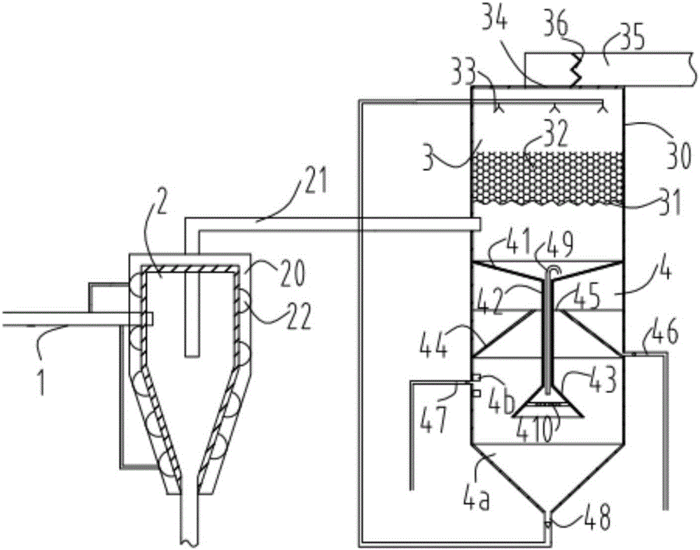
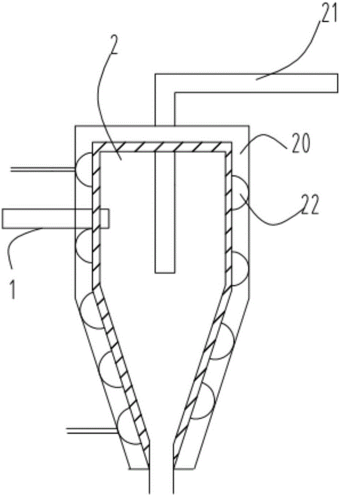
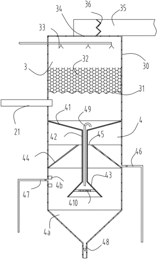
[0031] figure 1 Schematic diagram of the oil recovery system, figure 2 A schematic diagram of a cyclone dust collector, image 3 It is a schematic diagram of the spray treatment tower and the oil-water separator. like figure 1 , figure 2 and image 3As shown, what is provided in this embodiment is an oil recovery system, comprising a cyclone dust collector 2, a spray treatment tower 3 and an oil-water separator 4, the cyclone dust collector 2 is provided with a flue gas feed pipe 1, and the The cyclone dust collector 2 is connected before the spray treatment tower 3 through a gas delivery pipe 21, and the oil-water separator 4 is arranged directly below the spray treatment tower 3; the oil-water separator 4 and the spray treatment tower 3 The outer wall 30 is cylindrical and coaxially arranged, and the gas delivery pipe 21 is arranged between the spray treatment tower 3 and the oil-water separator 4; the oil-water separator 4 includes a conical inlet 41, a vertical chan...


PUM


Abstract

The invention relates to an oil recovery system, which comprises a cyclone dust remover, a spraying processing tower and an oil-water separator, wherein the cyclone dust remover is connected in front of the spraying processing tower through a gas conveying pipeline; the oil-water separator is arranged right under the spraying processing tower, and comprises a conical inlet, a vertical passage, a conical outlet and a conical separation plate; an annular outlet is formed between the conical separation plate and the vertical passage; the lower end of the oil-water separator is provided with a sedimentation chamber; the lowest end of the sedimentation chamber is provided with a water discharge passage; the water discharge passage is connected onto a spray head arranged in the spraying processing tower. The oil recovery system solves the problem that heavy oil and light oil cannot be directly separated; the heavy oil and the light oil directly complete the separation in the collection stage; the heavy oil, the light oil and dust are more thoroughly removed from smoke gas, so that the equipment operation is smoother.

Description

technical field [0001] The invention relates to an oil recovery system, in particular to a device for treating high-temperature flue gas generated during the drying and pyrolysis carbonization of oily sludge. Background technique [0002] According to statistics, my country's oil production industry produces more than one million tons of oily sludge. Oily sludge contains a large amount of petroleum hydrocarbons. If it is not used, it will not only waste oil and gas resources, but also because of the high water content, the sludge volume is relatively large, and it needs to occupy a large area of ​​land for storage or landfill, which is easy to pollute the environment. . Treatment technologies for oily sludge at home and abroad include incineration, biological treatment and pyrolysis. As a more effective resource treatment technology, the pyrolysis and carbonization of oily sludge is gradually adopted by the industry. [0003] The invention with the application number 2015...

Claims


Application Information

Patent Timeline
IPC IPC(8): B01D50/00B01D45/16B01D47/14B01D47/05
CPCB01D45/16B01D47/05B01D47/14B01D2247/04B01D50/40
Inventor 叶玉芳叶华健
Owner CHANGXING JINNUO MACHINERY CO LTD
Why Eureka
Try Eureka