A flue gas desulphurization denitration method including flue gas temperature control and a device therefor

A flue gas and denitrification technology, applied in the denitration method, can solve the problems of increasing operating costs and increasing the amount of ammonia gas.

Active Publication Date: 2016-06-22
ZHONGYE-CHANGTIAN INT ENG CO LTD
View PDF14 Cites 15 Cited by
  • Summary
  • Abstract
  • Description
  • Claims
  • Application Information

AI Technical Summary

Problems solved by technology

In addition, SO in flue gas 3 , HF, and HCl will also react with NH 3 reaction, for denitrificatio

Method used


Image

  • A flue gas desulphurization denitration method including flue gas temperature control and a device therefor
  • A flue gas desulphurization denitration method including flue gas temperature control and a device therefor
  • A flue gas desulphurization denitration method including flue gas temperature control and a device therefor

Examples


specific Embodiment approach

[0107] The mixing device (M) used in the following embodiments comprises an air pipeline 602, an ammonia gas pipeline 606, an air helical section 609, an ammonia gas helical section 610, a mixing section 612 and a mixed gas outlet 616, wherein the ammonia gas pipeline 606 is from One side of the larger air duct 602 of diameter is inserted (or extends into) in the air duct, bends then and extends a certain distance L (it is for example 20-80 of the total length of the mixing device) along the air duct 602 axis along the airflow direction. %, more preferably 35-65%, such as L=0.2-2 meters, preferably 0.3-1.5 meters), the end section of the ammonia gas pipeline 606 is the ammonia gas helical section 610, and the ammonia gas helical section 610 is comprised by the ammonia gas pipeline 606 m helical ammonia passages separated by m longitudinally extending spiral plates 608, in addition, the air helical section 609 corresponding to the ammonia helical section 610 includes a space bet...

Embodiment approach 1

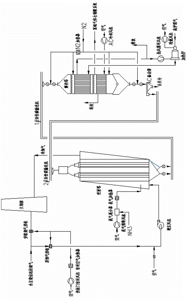
[0118] use figure 1 The process and adsorption tower shown in (such as figure 1 and 2).

[0119] Activated carbon adsorption tower device includes

[0120] 1) adsorption tower (1),

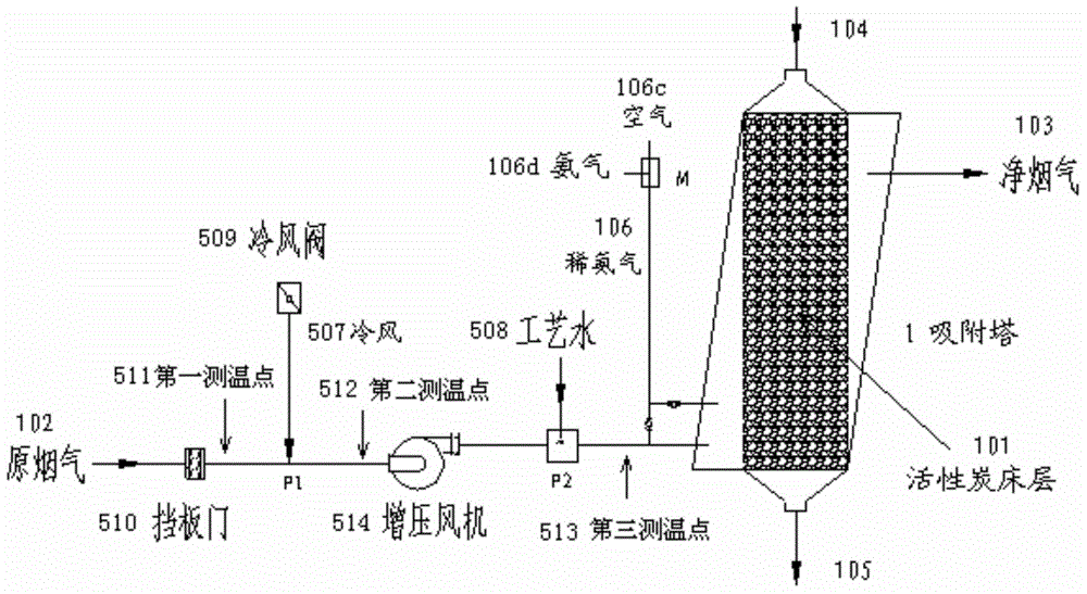
[0121] 2) the original flue gas conveying flue 102 upstream of the flue gas input port of the adsorption tower, wherein a cold air inlet is provided on the upstream position P1 of the flue, and a process water nozzle is provided on the downstream position P2 of the flue,

[0122] 3) A cooling fan 509 connected to the cold air inlet at the P1 position,

[0123] 4) The process water delivery pipeline 508 connected with the process water nozzle on the P2 position,

[0124] 5) a booster blower 514 located between the P1 and P2 positions, and

[0125] 6) ammonia delivery pipeline 106, on this pipeline 106 is provided with ammonia and air mixing device M (as Figure 6 Ammonia-air mixing device M of the present invention shown in . m=2 and n=2. The outer diameter of the ammonia pipeline is 33 c...

Embodiment approach 2

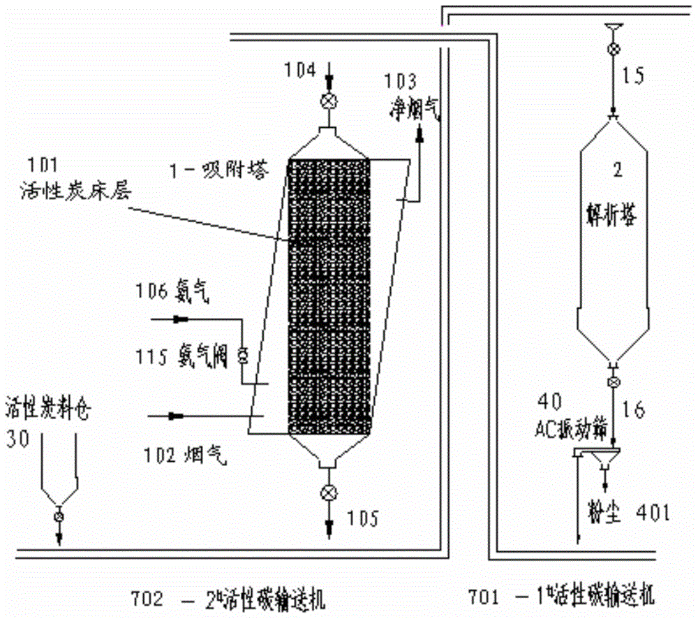
[0138] Repeat Embodiment 1, just use image 3 The adsorption tower shown in the figure 1 The adsorption tower shown in. The tower height of the adsorption tower is 24.5 meters. Flow rate of hot flue gas from sintering machine 6.5×10 5 N m 3 / h, humidity 8.1%.

[0139] The flue gas temperature in the adsorption tower is the average value of the flue gas temperatures in the two interstitial spaces between the three beds.

[0140] The temperature of the flue gas entering the adsorption tower (or the temperature of the activated carbon bed) remains relatively stable at around 140°C.


PUM


Abstract

A flue gas desulphurization denitration method including flue gas temperature control in an activated-carbon adsorption column and a device therefor are provided. The method includes I) a step of flue gas temperature control and II) a step of desulphurization and denitration, wherein the step of flue gas temperature control comprises (1) a step of subjecting flue gas to first time of cooling by feeding cold air into a flue conveying high-temperature flue gas to the activated-carbon adsorption column from a cold-air inlet at an upstream position (P1) of the flue, and (2) spraying cooling water or cold water mist into the flue gas in the flue from a process water spray nozzle at the downstream position (P2) of the position (P1) from which the cold air is fed, adjusting the temperature of the flue gas fed into the adsorption column to be in a preset range of T3, for example, the T3 ranges from 105-150 DEG C. The temperature of the flue gas fed into the adsorption column is controlled by mixing with the cold air and spraying water.

Description

technical field [0001] The present invention relates to flue gas desulfurization and denitrification methods using activated carbon adsorption towers. More specifically, the present invention relates to a method for cooling the flue gas (sintering flue gas) at the upstream or front end of the activated carbon adsorption tower by spraying water and cooling air at the same time. Measures to control the temperature of the flue gas entering the adsorption tower in the range of 100-150°C, preferably in the range of 120-140°C, these belong to the field of sintering flue gas treatment. Background technique [0002] For industrial flue gas, especially sintering machine flue gas in the iron and steel industry, it is ideal to use large-scale dry desulfurization and denitrification devices and processes including activated carbon adsorption towers and desorption towers. Activated carbon flue gas purification technology has the characteristics of simultaneous desulfurization and denitri...

Claims


Application Information

Patent Timeline
IPC IPC(8): B01D53/76B01D53/60
CPCY02A50/20
Inventor 魏进超叶恒棣张震孙英刘昌齐
Owner ZHONGYE-CHANGTIAN INT ENG CO LTD
Why Eureka
Try Eureka