Cooling system used for medical imaging device

A medical imaging and cooling system technology, applied in the field of medical instruments, can solve the problems of inability to maintain the temperature stability between scans, difficult to guarantee the operating temperature of the system, affecting the imaging effect and system life, etc., to achieve compact structure, simplified structure, maintenance The effect of stability

Active Publication Date: 2016-06-22
SHANGHAI UNITED IMAGING HEALTHCARE
View PDF6 Cites 14 Cited by
  • Summary
  • Abstract
  • Description
  • Claims
  • Application Information

AI Technical Summary

Problems solved by technology

A more commonly used cooling method is to directly pump out the air in the scanning room to take away the heat inside the machine, but this method cannot maintain the stability of the temperature in the scanning room, and it is difficult to ensure that the system runs at the best working temperature. It is easy to bring dust and impurities in the environment into the detector, affecting the imaging effect and system life

Method used


Image

  • Cooling system used for medical imaging device
  • Cooling system used for medical imaging device
  • Cooling system used for medical imaging device

Examples


Embodiment 1

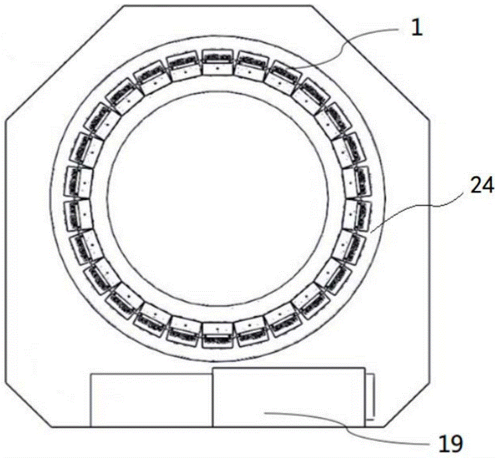
[0034] see figure 1 , the positron emission tomography apparatus includes a channel for accommodating patients, the support structure 24 outside the channel is provided with detector modules 1 arranged circumferentially around the channel, and the cooling device 19 is provided at the lower part of the scanner.

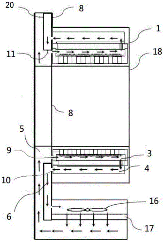
[0035] figure 2 It is a cross-sectional view of a positron emission tomography imaging device. The number 8 in the figure refers to a second partition, and a plurality of detector modules 1 are arranged on one side of the second partition 8, and a guide channel is arranged on the other side.

[0036] The diversion channel is a cavity, surrounded by a plurality of side plates, wherein the second partition 8 is one of the side plates forming the cavity; a third partition is arranged in the diversion channel , the third dividing plate is formed by connecting the baffle plate 11 and the channel cover plate 20, and divides the cavity into an air inlet channel 5 and a retu...

Embodiment 2

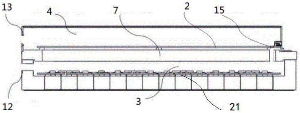
[0040] The difference between this embodiment and the first embodiment lies in the structure of the detector module 1. In this embodiment, the detector module 1 has a hollow chamber, and a first partition 7 is arranged inside the detector module 1; the detector module 1 The side connected to the second partition 8 is a fully open structure, the front end of the first partition 7 is tightly against the outer wall of the second partition 8, and the end of the second partition 7 is provided with a fifth ventilation hole 15 , the first partition 7 divides the interior of the detector module 1 into an air inlet chamber 3 and a return air chamber 4, the air inlet chamber 3 directly communicates with the air inlet passage 5 through the second through hole 10 on the second partition 8, and the return air chamber The air chamber 4 directly communicates with the return air passage 6 through the first ventilation hole 9 on the second partition 8 , and the air inlet chamber 3 and the retur...

Embodiment 3

[0042] see Figure 5 The difference from the first embodiment above is that in this embodiment, the hollow chamber inside the detector module 1 is divided into the air inlet chamber 3 and the air return chamber 4 by the first partition 7; the front-end processing unit 21 is located in the air inlet chamber 3, the front-end processing unit 21 is installed on the inner wall of the detector module 1, the readout circuit board 2 is located in the return air cavity 4, and one end of the readout circuit board 2 is installed on the inner wall of the detector module 1 through a connector, and its The other end is not in contact with the detector module 1; the shape of the detector module 1 is approximately cuboid, and a side wall of the detector module 1 can be connected with the second partition 8, and the side wall is provided with a wall connected to the air inlet chamber 3. The third ventilation hole 12 communicates with the fourth ventilation hole 13 of the return air chamber 4, ...


PUM


Abstract

The invention relates to the technical field of medical instruments, specifically to a cooling system used for a medical imaging device. The medical imaging device includes a detector module having a hollow cavity, a reading circuit board and a front-end processing unit are arranged in the hollow cavity. The cooling system includes a cooling air passage and a flow guide channel, wherein the cooling air passage includes an air inlet cavity and an air return cavity, the front-end processing unit is located in the air inlet cavity, and the reading circuit is located in the air return cavity; and the flow guide channel includes an air inlet channel and an air return channel arranged side by side, the air inlet channel is communicated with the air inlet cavity, the air return channel is communicated with the air return cavity, and a refrigeration device is used for conveying cooling air flow to the air inlet channel. According to the cooling system used for the medical imaging device, the reading circuit board is integrated in the detector, and a cooling circulation system is established, thereby improving stability of temperature inside the detector module, and the cooling system is compact in structure and reasonable in layout, thereby providing convenience for maintenance of the detector module.

Description

technical field [0001] The invention relates to the technical field of medical instruments, in particular to a cooling system for medical imaging devices. Background technique [0002] Existing medical imaging technologies include Single-Photon Emission Computed Tomography (Single-Photon Emission Computed Tomography, SPECT), Positron Emission Tomography (Position Emission Tomography, PET) and other technologies. Medical imaging systems such as SPECT and PET include a channel for accommodating patients, and detectors surrounding the human body are arranged in the channel, so that multi-angle imaging pictures of human lesion tissues can be obtained, and more accurate lesion information can be obtained. [0003] The principle of positron emission tomography technology is: a positron emitted during the decay of positronium combines with free electrons in human tissue and annihilates, and transforms into two gamma photons with opposite directions and energy of 511KeV each. When ...

Claims


Application Information

Patent Timeline
Patent Type & Authority Applications(China)
IPC IPC(8): H05K7/20
CPCH05K7/20145G01T1/1648G01T1/2985A61B6/037A61B6/4488H01L31/024G01J5/061G01T1/244G01T1/249
Inventor 刘伟平孙宜兴
Owner SHANGHAI UNITED IMAGING HEALTHCARE
Why Eureka
Try Eureka