A cooling system for medical imaging device
A medical imaging and cooling system technology, applied in the field of medical instruments, can solve the problems of difficulty in ensuring the operating temperature of the system, inability to maintain the temperature stability between scans, affecting imaging effects and system life, etc. The effect of stability
- Summary
- Abstract
- Description
- Claims
- Application Information
AI Technical Summary
Problems solved by technology
Method used
Image
Examples
Embodiment 1
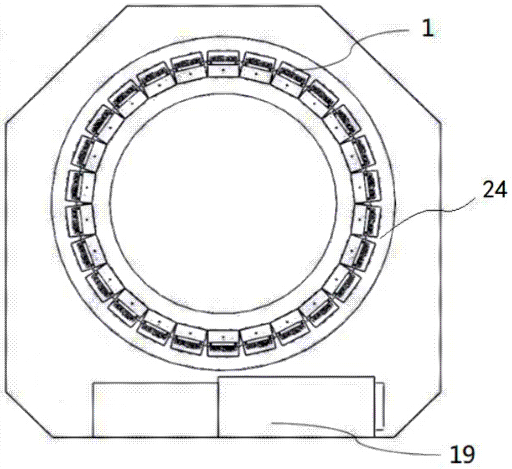
[0034] see figure 1 , the positron emission tomography apparatus includes a channel for accommodating patients, the support structure 24 outside the channel is provided with detector modules 1 arranged circumferentially around the channel, and the cooling device 19 is provided at the lower part of the scanner.
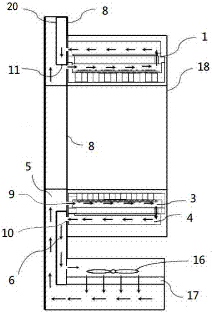
[0035] figure 2 It is a cross-sectional view of a positron emission tomography imaging device. The number 8 in the figure refers to a second partition, and a plurality of detector modules 1 are arranged on one side of the second partition 8, and a guide channel is arranged on the other side.
[0036] The diversion channel is a cavity, surrounded by a plurality of side plates, wherein the second partition 8 is one of the side plates forming the cavity; a third partition is arranged in the diversion channel , the third dividing plate is formed by connecting the baffle plate 11 and the channel cover plate 20, and divides the cavity into an air inlet channel 5 and a retu...
Embodiment 2
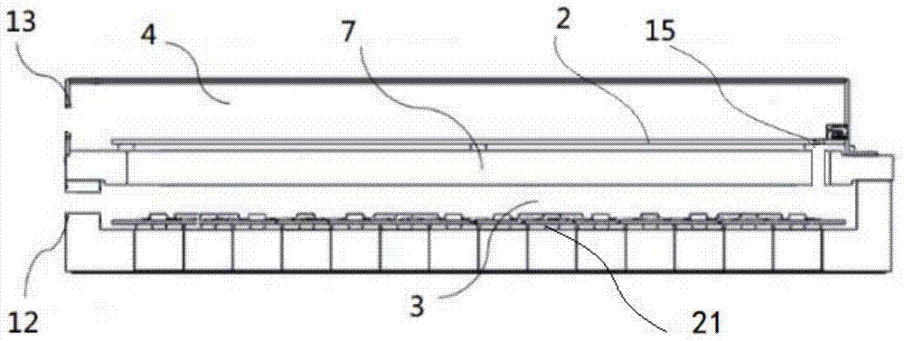
[0040] The difference between this embodiment and the first embodiment lies in the structure of the detector module 1. In this embodiment, the detector module 1 has a hollow chamber, and a first partition 7 is arranged inside the detector module 1; the detector module 1 The side connected to the second partition 8 is a fully open structure, the front end of the first partition 7 is tightly against the outer wall of the second partition 8, and the end of the second partition 7 is provided with a fifth ventilation hole 15 , the first partition 7 divides the interior of the detector module 1 into an air inlet chamber 3 and a return air chamber 4, the air inlet chamber 3 directly communicates with the air inlet passage 5 through the second through hole 10 on the second partition 8, and the return air chamber The air chamber 4 directly communicates with the return air passage 6 through the first ventilation hole 9 on the second partition 8 , and the air inlet chamber 3 and the retur...
Embodiment 3
[0042] see Figure 5 The difference from the first embodiment above is that in this embodiment, the hollow chamber inside the detector module 1 is divided into the air inlet chamber 3 and the air return chamber 4 by the first partition 7; the front-end processing unit 21 is located in the air inlet chamber 3, the front-end processing unit 21 is installed on the inner wall of the detector module 1, the readout circuit board 2 is located in the return air cavity 4, and one end of the readout circuit board 2 is installed on the inner wall of the detector module 1 through a connector, and its The other end is not in contact with the detector module 1; the shape of the detector module 1 is approximately cuboid, and a side wall of the detector module 1 can be connected with the second partition 8, and the side wall is provided with a wall connected to the air inlet chamber 3. The third ventilation hole 12 communicates with the fourth ventilation hole 13 of the return air chamber 4, ...
PUM
 Abstract
Description
Claims
Application Information
 - R&D
- Intellectual Property
- Life Sciences
- Materials
- Tech Scout
- Unparalleled Data Quality
- Higher Quality Content
- 60% Fewer Hallucinations
Browse by: Latest US Patents, China's latest patents, Technical Efficacy Thesaurus, Application Domain, Technology Topic, Popular Technical Reports.
© 2025 PatSnap. All rights reserved.Legal|Privacy policy|Modern Slavery Act Transparency Statement|Sitemap|About US| Contact US: help@patsnap.com


