Flue gas deep purification system adopting phase-change coagulation and charged processing integration

A flue gas deep purification and purification system technology, applied in chemical instruments and methods, dispersed particle separation, combined devices, etc., can solve problems such as restricting ultra-low emission technology route selection and construction schedule, inability to provide temperature gradients, difficulties, etc. Achieve the effect of saving investment cost, simple operation and improving removal effect

Inactive Publication Date: 2016-06-29
GUODIAN SCI & TECH RES INST
View PDF4 Cites 1 Cited by
  • Summary
  • Abstract
  • Description
  • Claims
  • Application Information

AI Technical Summary

Problems solved by technology

[0004] Among them, ultra-low emission requires that under the condition of a reference oxygen content of 6%, the emission concentration of smoke and dust should not be higher than 10 mg / m3; however, most of the active units are old units, and the ultra-low emission technology is restricted due to site and space constraints. Route selection and schedule
[0005] Chinese patent ZL201420655999.9 provides a flue gas deep purification device for large-scale coal-fired power plants. A two-phase rectification and coagulation system is installed at the flue gas inlet. Grille, the grille is set as a single layer or multiple layers, but it is difficult to adopt this process for units with a relatively compact site and space after the desulfurization system
However, in the wet electrostatic precipitator system involved in the above two patents (ZL201410522652.1 and ZL201410617916.1), the cathode and anode systems are under flue gas conditions, which cannot provide such a temperature gradient

Method used


Image

  • Flue gas deep purification system adopting phase-change coagulation and charged processing integration
  • Flue gas deep purification system adopting phase-change coagulation and charged processing integration
  • Flue gas deep purification system adopting phase-change coagulation and charged processing integration

Examples


Embodiment Construction

[0025] The present invention will be further described below in conjunction with the accompanying drawings.

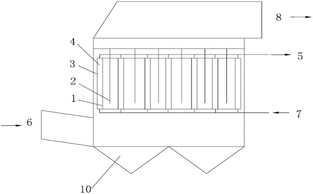
[0026] Such as figure 1 and figure 2 As shown, the flue gas deep purification system integrated with phase change condensation and charging includes a flue gas inlet, a flue gas outlet, a circulating cooling water outlet 5, a circulating cooling water inlet 7, multiple purification units A and a liquid collection tank 10, and the flue gas The inlet, the flue gas outlet, the circulating cooling water outlet 5 and the circulating cooling water inlet 7 are all connected to the purification unit A; the purification unit A is vertically arranged in the purification system, and the purification units A are fixed by welding or gluing along each side ; The sump 10 is set at the bottom of the purification system.

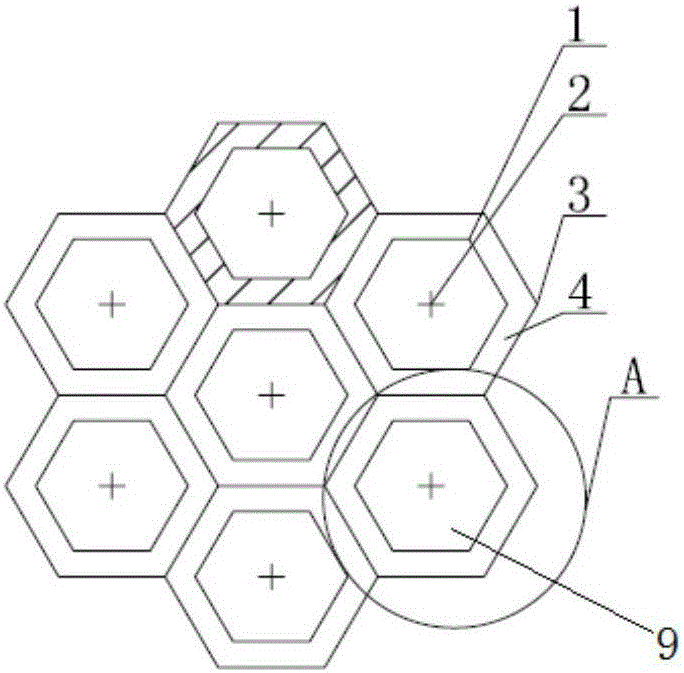
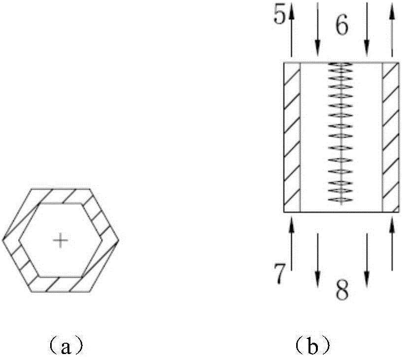
[0027] Such as image 3 As shown, the shape of each purification unit A is set to be hexagonal, square or circular. Each purification unit A includes an anode p...


PUM


Abstract

The invention provides a flue gas deep purification system adopting phase-change coagulation and charged processing integration. The system comprises a flue gas inlet, a flue gas outlet, a cooling medium inlet, a cooling medium outlet, multiple purification units and a liquid collecting tank, wherein the cooling medium inlet and the cooling medium outlet are communicated with the purification units, and the liquid collecting tank is arranged at the bottom of the purification system; the purification units are vertically arranged in the purification system and are fixedly connected, each purification unit comprises anode plates, an inner cavity, cathode wires and a circulating cooling device, the anode plates are mutually connected to form the inner cavity, the cathode wires are arranged in the inner cavity, wet flue gas flows in the inner cavity, the circulating cooling device is arranged on the peripheries of the anode plates, a cooling medium flows in the device and is input from the bottom and output from the top, and the flowing direction of the cooling medium is opposite to that of the wet flue gas; the wall surface temperature of each anode plate is adjustable. According to the system, deep purification charged processing and phase-change coagulation are integrally designed, and through combination of fine-particle coagulation and large-particle charged removing effect, the particle removing effect is improved; transformation is not limited by field and space.

Description

technical field [0001] The invention relates to a flue gas deep purification system integrated with phase change condensation and charging, and belongs to the field of environmental protection in the electric power industry. Background technique [0002] By the end of 2014, the emission of air pollutants from thermal power plants had dropped rapidly, achieving the largest drop since the "Eleventh Five-Year Plan": Among them, the emission of power smoke and dust fell from about 4 million tons in 2005 to 980,000 tons in 2014, unit The smoke and dust emission of thermal power generation is 0.23 g / kWh; among them, the proportion of electric dust collector, bag filter and electric bag composite dust collector in coal-fired power plants accounted for 77.3%, 9.0% and 13.7% of the national coal-fired unit capacity respectively. Although the reduction of pollutants in the power industry has achieved significant results, smog and haze still occur frequently, and the environmental prot...

Claims


Application Information

Patent Timeline
Patent Type & Authority Applications(China)
IPC IPC(8): B01D50/00B01D51/02
CPCB01D50/00B01D51/02
Inventor 薛建明刘建民柏源管一明
Owner GUODIAN SCI & TECH RES INST
Why Eureka
Try Eureka