Design method for improving fuel injecting and mixing in super-combustion combustion room

A design method and combustion chamber technology, applied in the combustion method, combustion chamber, combustion equipment and other directions, can solve the problems of easy thermal erosion of the plug-in structure, unsatisfactory mixing effect, large total pressure loss, etc., so as to increase the thrust , Reduced size, small total pressure loss effect

Active Publication Date: 2016-06-29
XIAMEN UNIV
View PDF6 Cites 12 Cited by
  • Summary
  • Abstract
  • Description
  • Claims
  • Application Information

AI Technical Summary

Problems solved by technology

[0004] At present, the fuel injection layout in the super-combustion combustor is mainly divided into the following two types: one is the wall injection layout, which is characterized in that the fuel is injected vertically or obliquely from the wall of the combustion chamber, the mixing efficiency is high and the flame is stable, but the overall The pressure loss is large; the other is the plug-in injection layout, that is, the fuel injector is installed in the center of the combustion chamber channel, and the fuel is injected into the air in parallel, so that the engine directly uses the fuel injection momentum as thrust to increase the thrust of the combustion chamber. Its total pressure loss is small but the mixing effect is not ideal, and the plug-in structure is vulnerable to thermal erosion

Method used


Image

  • Design method for improving fuel injecting and mixing in super-combustion combustion room
  • Design method for improving fuel injecting and mixing in super-combustion combustion room
  • Design method for improving fuel injecting and mixing in super-combustion combustion room

Examples


Embodiment Construction

[0025] The present invention will be described in further detail below in conjunction with the accompanying drawings.

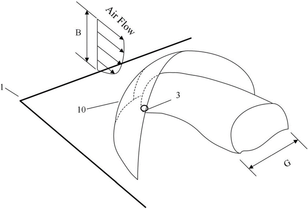
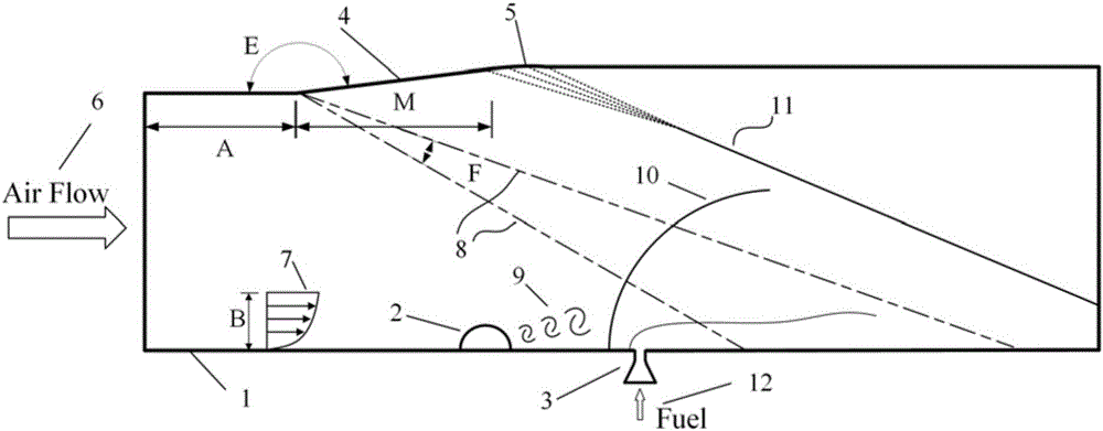
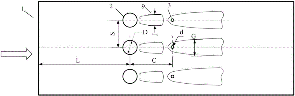
[0026] see Figure 1~4 , the design method for promoting fuel injection and mixing in a superburning combustor is provided with a superburning combustor 1, a hemispherical vortex generator 2, a circular fuel nozzle 3, an expansion section 4, and an isentropic compression section 5. The superfiring combustor 1 is a conventional rectangular combustor, the cross-section of the internal flow passage is rectangular, and the main flow (AirFlow) 6 in the passage is supersonic air; Upstream of the circular fuel nozzle 3, the vortex structure 9 produced by it can promote the mixing of downstream fuel and air; the circular fuel nozzle 3 is generally convergent, and the fuel 12 can be vertically injected into the super-combustion combustion through the circular nozzle. In the chamber 1, the central axis is collinear with the central axis of the hemispherical vortex gen...


PUM


Abstract

The invention discloses a design method for improving fuel injecting and mixing in a super-combustion combustion room and relates to scramjet engines. The design method includes the steps that firstly, the diameter and the number of round fuel nozzles are determined according to the total flow of needed fuel, numerical calculation is conducted on a calculating example only with the single round fuel nozzle, and the diffusion diameter and the wall face boundary layer development rule of the fuel are obtained; secondly, the diameters and the positions of semispherical vortex generators are determined; thirdly, the positions of the round fuel nozzles are determined; fourthly, the center distance between every two adjacent semispherical vortex generators is determined; fifthly, the turning angle, the length and the position of an expansion section are determined; and finally, an isentropic compression section is used for transition connection of the expansion section and the upper wall face of the super-combustion combustion room, and therefore design of an injection system of the whole super-combustion combustion room is completed. The working efficiency of the super-combustion combustion room is improved, the size of the super-combustion combustion room is reduced, the weight of the super-combustion combustion room is reduced, engine thrust is increased, and fuel tissue can be better stably combusted; and total pressure losses are low, thermal loads are low, and the thermal protection difficulty of the structure in the super-combustion combustion room is lowered.

Description

technical field [0001] The invention relates to a scramjet engine, in particular to a design method for improving fuel injection and mixing in a scramjet combustion chamber. Background technique [0002] Scramjet is the preferred power system to achieve hypersonic flight. It has the advantages of high specific impulse performance, simple structure, light weight and fast speed. It is widely used in aerospace aircraft, hypersonic aircraft and hypersonic cruise missiles and other fields. [0003] Among the problems involved in the scramjet engine, how to achieve efficient fuel injection, blending and stable ignition and combustion is one of the key issues. Since the supersonic mainstream stays in the scramjet channel for only a few milliseconds, in such a short time and space, it is difficult for the air and fuel in the combustion chamber to mix efficiently and burn stably. Therefore, the fuel injection and mixing efficiency directly determine the working efficiency of the scr...

Claims


Application Information

Patent Timeline
Patent Type & Authority Applications(China)
IPC IPC(8): F23R3/16
CPCF23R3/16
Inventor 周驯黄滕健李怡庆王李璨尤延铖
Owner XIAMEN UNIV
Why Eureka
Try Eureka