Continuous circulation carbon dioxide capture system on basis of in-situ adsorption/desorption modes

A carbon dioxide and carbon capture technology, applied in separation methods, chemical instruments and methods, dispersed particle separation, etc., can solve the problems of limited gas-solid reaction rate improvement space, complex serial double fluidized bed system, poor wear resistance, etc. , to achieve the effects of promoting the heating process and overall reaction efficiency, improving carbon capture reaction efficiency, and reducing production costs

Active Publication Date: 2016-07-06
HUAZHONG UNIV OF SCI & TECH
View PDF4 Cites 16 Cited by
  • Summary
  • Abstract
  • Description
  • Claims
  • Application Information

AI Technical Summary

Problems solved by technology

[0005] However, further studies have shown that the technology still has several technical challenges
First of all, the wear resistance of alkali metal oxides and alkaline earth metal oxides is generally poor, and they are too severely broken in the traditional serial double fluidized bed reactor; secondly, due to the limitation of thermodynamics, the adsorption The temperature difference between the adsorption and desorption reaction is relatively large. For example, the temperature difference between the adsorption and desorption of CaO is 350°C, and the temperature difference between the adsorption and desorption of MgO is 250°C. Therefore, the thermal economy of the traditional process is poor; The system with double fluidized beds is complex, inconvenient to operate and limits the room for further improvement of the gas-solid reaction rate

Method used


Image

  • Continuous circulation carbon dioxide capture system on basis of in-situ adsorption/desorption modes
  • Continuous circulation carbon dioxide capture system on basis of in-situ adsorption/desorption modes
  • Continuous circulation carbon dioxide capture system on basis of in-situ adsorption/desorption modes

Examples


Embodiment Construction

[0031] In order to make the object, technical solution and advantages of the present invention clearer, the present invention will be further described in detail below in conjunction with the accompanying drawings and embodiments. It should be understood that the specific embodiments described here are only used to explain the present invention, not to limit the present invention. In addition, the technical features involved in the various embodiments of the present invention described below can be combined with each other as long as they do not constitute a conflict with each other.

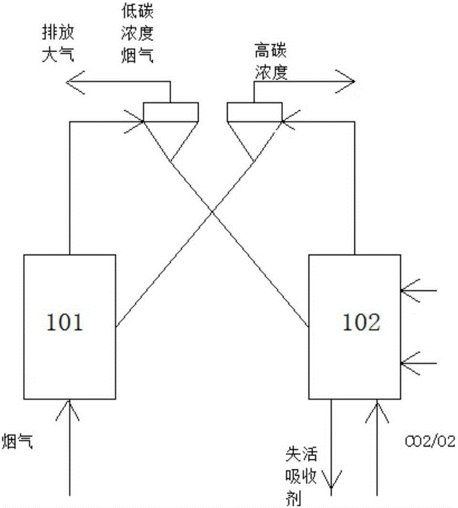
[0032] figure 1 A schematic diagram of the main structure of a fluidized bed system for variable temperature carbon capture based on a solid adsorbent in the prior art is shown. Such as figure 1 As shown in , in this traditional serial double fluidized bed reactor, the carbonation reactor and the regeneration reactor are arranged separately in different positions of the reaction path, and the ...


PUM


Abstract

The invention belongs to the field of equipment related to carbon capture technologies, and discloses a continuous circulation carbon dioxide capture system on the basis of in-situ adsorption/desorption modes.The continuous circulation carbon dioxide capture system comprises a flue gas purification module, a pressurization module, an isothermal circulation carbon capture reactor group, a gas outlet condensation device, a negative-pressure module and the like which are sequentially connected with one another.The designed isothermal circulation carbon capture reactor group comprises a carbonization reactor and a regeneration reactor which cling to each other to transfer heat, and functions of the carbonization reactor and the regeneration reactor can be switched over after reaction is carried out for a certain time; the carbonization reactor is provided with the pressurization module, the regeneration reactor (42) is provided with the negative-pressure module, and an appropriate quantity of water vapor can be continuously supplied for the regeneration reactor (42).The continuous circulation carbon dioxide capture system has the advantages that the integral reaction efficiency can be obviously improved as compared with existing continuous carbon capture modes, abrasion of solid adsorbent particles due to collision can be eliminated, temperature difference between adsorption and desorption can be reduced to a great extent, the continuous circulation carbon dioxide capture system is economical and environmentally friendly, and the like.

Description

technical field [0001] The invention belongs to the field of equipment related to carbon capture technology, and more specifically relates to a carbon continuous cycle capture system based on an in-situ adsorption / desorption method. Background technique [0002] carbon dioxide (CO 2 ) is one of the main components of greenhouse gases that cause global warming, and contributes as much as 55% to the greenhouse effect. Due to CO 2 Climate change caused by greenhouse gas emissions has become the focus of attention around the world. Carbon capture and storage technology (CCS technology) refers to a technology that captures and separates carbon dioxide from related concentrated emission combustion sources, and uses various methods to store it to avoid its emission into the atmosphere. It is the most effective way to deal with climate change. One of the technical paths. Among them, compared to CO 2 Compression, transportation and storage, capture of CO in flue gas from coal-fir...

Claims


Application Information

Patent Timeline
Patent Type & Authority Applications(China)
IPC IPC(8): B01D53/81B01D53/62
CPCB01D53/62B01D53/81B01D2251/40B01D2251/402B01D2251/404B01D2257/504Y02A50/20Y02C20/40
Inventor 罗聪徐勇庆郑瑛丁浩然王琪瑶张立麒赵海波
Owner HUAZHONG UNIV OF SCI & TECH
Why Eureka
Try Eureka