
Oxide target material and preparation method thereof

A technology of oxides and targets, which is applied in metal material coating process, ion implantation plating, coating, etc., can solve the problems of uneven sintering stress and cracking of targets, and reduce the risk of cracking, reduce cracks and even Cracking, the effect of reducing variance

Active Publication Date: 2016-07-06
GRIKIN ADVANCED MATERIALS
View PDF5 Cites 12 Cited by
  • Summary
  • Abstract
  • Description
  • Claims
  • Application Information

AI Technical Summary

Problems solved by technology

[0004] Due to the direct high-density sintering of high-purity materials, it is easy to cause problems such as inhomogeneity and sintering stress inside the target
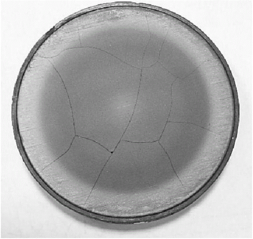
In fact, after the ideal sintered blank is obtained through a suitable sintering process, the target will suffer thermal shock under the high power in the sputtering process, and cracking will occur, and with the increase in the size of the oxide target , the problem is getting worse

Method used


Image

  • Oxide target material and preparation method thereof
  • Oxide target material and preparation method thereof
  • Oxide target material and preparation method thereof

Examples


Embodiment 1

[0025] Example 1: Al 2 o 3 Target preparation

[0026] Using 99.99% high-purity Al 2 o 3 The powder is uniformly mixed, then evenly spread in a hot-pressing mold with a diameter of 165mm, and then evenly pressed, and finally pressurized at 1400°C for densification and sintering to obtain Al 2 o 3 Target blank.

[0027] The detected Al 2 o 3 The relative density of the target blank is 99.5%; then the whole block of Al is scanned by ultrasonic C 2 o 3 The target blank is scanned, and the internal information of the target blank is detected according to the ultrasonic wave, and the density uniformity fluctuation of each part of the target blank is evaluated, and the fluctuation is not more than 5%.

[0028] Al will be obtained 2 o 3 The target blank is cut and processed into a size of Al 2 o 3 Target blank; then in Al 2 o 3 The outer edge of the sputtering surface of the target blank is processed with a chamfer 403, the angle is 45°, and the height H is 2.5mm; 2...

Embodiment 2

[0031] Embodiment 2: Preparation of MgO target material

[0032] Use 99.99% high-purity MgO powder for uniform powder mixing, then evenly spread it in a hot-pressing mold with a diameter of 215mm, and then apply pressure evenly, and finally pressurize at 1400°C for densification and sintering to obtain the MgO target blank.

[0033] The relative density of the MgO target blank obtained through testing is 99.5%; then the entire MgO target blank is scanned by ultrasonic C-scanning, and the internal information of the target blank is detected according to the ultrasonic wave, and the density uniformity fluctuation of each part of the target blank is evaluated. Its volatility is not greater than 5%.

[0034] The obtained MgO target blank is cut and processed into a size of MgO target blank; then process a fillet 504 on the outer edge of the sputtering surface of the MgO target blank, the radius R of the fillet is 2.5mm; the thickness T1 of the first main sputtering region 501 of t...


PUM


Abstract

The invention belongs to the technical field of target material preparation and discloses an oxide target material and a preparation method thereof. Chamfers or round corners are machined on the edge of a sputtering surface of the oxide target material, groove structures are machined in a non-main-sputtering area of the sputtering surface, and chambers are machined at all the turning corners. The oxide comprises one or more of Al2O3, TiO2, Nb2O5, HfO2, La2O3, ZnO, MgO, ITO, AZO and IGZO. The preparation method comprises the steps that high-purity oxide powder is prepared into an oxide target billet through a sintering technique, then the chamfers or the round corners are machined on the edge of the sputtering surface of the oxide target billet through machining, the groove structures are machined in the non-main-sputtering area, the chamfers are machined at all the turning corners, and in this way, the oxide target material is formed. Through the optimum structural design for the oxide target material, the risk that the target material cracks in the sputtering process is reduced, and high-quality sputtering sputter coating is achieved.

Description

technical field [0001] The invention belongs to the technical field of target material preparation, and in particular relates to an oxide target material and a preparation method thereof. Background technique [0002] Oxide targets include Al 2 o 3 、TiO 2 , Nb 2 o 5 , HfO 2 , La 2 o 3 , ZnO, MgO, ITO, AZO, IGZO and other single oxides and various composite oxide materials. Oxide targets play an important role in the fields of integrated circuits, flat-panel displays, and solar energy due to their high dielectric constant, transparent conductivity, and other properties. Sputtering is a commonly used method to prepare various oxide functional films, but due to the high brittleness and high hardness of oxide targets, high-density oxide targets are very easy to crack, especially for large-size targets. After the finished target is processed, cracks will also occur due to the thermal load during the sputtering process, which will affect the quality of the oxide film and ...

Claims


Application Information

Patent Timeline
IPC IPC(8): C23C14/34
CPCC23C14/3407C23C14/3414
Inventor 何金江徐学礼陈淼琴万小勇丁照崇熊晓东李勇军
Owner GRIKIN ADVANCED MATERIALS
Learn More