A method and device for purifying exhaust gas from an oil storage tank

An oil storage tank and exhaust gas technology is applied in the field of oil and gas recovery devices for recovering hydrocarbons from volatile oil and gas in tank areas. Emissions, reduce condensation energy consumption, ensure the effect of safe operation

Active Publication Date: 2018-04-10
CHINA PETROLEUM & CHEM CORP +1
View PDF8 Cites 0 Cited by
  • Summary
  • Abstract
  • Description
  • Claims
  • Application Information

AI Technical Summary

Problems solved by technology

When activated carbon adsorbs oil and gas components, the adsorption and heat release will cause a large temperature rise in the activated carbon bed, especially when the concentration of oil and gas is high, the activated carbon bed is prone to local overheating, thereby reducing the service life of the adsorbent and making the operation There are safety hazards in the process
[0005] CN1494454A describes a device that uses active carbon adsorption to recover organic matter. After the adsorption stops, the organic components are desorbed and adsorbed by steam, and then enter the condenser to condense and recover. A large amount of steam is introduced to condense, which increases the operating cost of the device.
CN1522785 discloses a method for recovering oil and gas, which compresses and cools the oil and gas, and absorbs it under pressurized conditions. Difficult to operate stably
This process is a combination of absorption and adsorption methods, and its disadvantages are that the process flow is long and the operating cost is high
[0008] As mentioned above, the existing oil and gas recovery technologies mainly have disadvantages such as high operating costs, low safety and reliability, and relatively low oil and gas recovery rates.

Method used


Image

  • A method and device for purifying exhaust gas from an oil storage tank

Examples


Embodiment 1

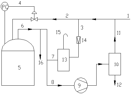
[0031] Such as figure 1 shown, four 5000m 3 The exhaled gas volume of the finished gasoline storage tank 5 is about 300m 3 / h, the gas phase space on the top of the oil storage tank is connected, and low-pressure gas is used as the protective gas on the top of the oil storage tank. The waste gas is collected into the gas compressor 9, and the gas compressor 9 adopts a liquid ring compressor, and the exhaust pressure of the gas compressor 9 shown is 0.4 MPa. The exhaust gas enters the condensation system 10 after being compressed, and is cooled to -30°C with low-temperature brine. When the pressure in the oil storage tank 5 reaches 1200Pa, start the gas compressor 9 to bleed air; when the pressure in the oil storage tank 5 reaches 600Pa, stop the gas compressor 9 to bleed air. When the pressure in the oil storage tank 5 is 200Pa, the pressure control and adjustment system 4 automatically replenishes the gas into the oil storage tank 5; when the pressure in the oil storage ta...


PUM


Abstract

The invention relates to a method and device for purifying exhaust gas from an oil storage tank. The purification device includes an oil storage tank, a water seal tank, a gas compressor, and a condensation system. The exhaust gas outlet on the top of the oil storage tank is divided into three routes. After passing through the gas compressor, it is connected to the condensing system, the second is connected to the exhalation port of the water-sealed tank, and the third is connected to the exhaust gas discharge port; the gas phase discharge port of the condensing system is connected to the low-pressure gas pipe network through pipelines, and the condensing system is Set the condensate discharge pipeline. The outlet of the low-pressure gas pipe network is divided into two routes. The first route is connected to the suction port of the water seal tank through the pressure reducing valve, and the second route is connected to the protective gas inlet of the oil storage tank. Gas flow control facilities are installed on the connecting pipeline between the gas pipeline network and the protective gas inlet of the oil storage tank, which together with the pressure detection facilities on the top of the oil storage tank constitute a pressure control and adjustment system. The method and device for purifying the exhaust gas of the oil storage tank of the present invention have the characteristics of safety, reliability, simple equipment, low investment and the like.

Description

technical field [0001] The invention relates to a method and device for purifying exhaust gas from an oil storage tank in the technical field of environmental protection and energy saving, in particular to an oil gas recovery device for recovering hydrocarbons from volatilized oil and gas in a tank area. Background technique [0002] Gasoline and other light oil products contain a large amount of light hydrocarbon components, which are highly volatile and easy to volatilize during storage and transportation. According to statistics, the oil lost by the escape of light oil products every year accounts for about 0.5% of light oil products. %. On the one hand, it produces huge energy waste and economic loss, on the other hand, it brings various hazards to production and the environment, such as fire and explosion, environmental pollution, and chronic or acute poisoning after inhalation. Therefore, oil and gas emission reduction and recovery technology has always been a key res...

Claims


Application Information

Patent Timeline
Patent Type & Authority Patents(China)
IPC IPC(8): F25J3/02F23G7/06
Inventor 廖昌建李经伟王海波戴金玲郭兵兵
Owner CHINA PETROLEUM & CHEM CORP
Why Eureka
Try Eureka