Photoetching machine projection objective and objective support through-hole design method
What is Al technical title?
Al technical title is built by PatSnap Al team. It summarizes the technical point description of the patent document.
A technology of projection objective lens and lithography machine, which is applied in the field of lithography machine, can solve problems such as increased temperature sensitivity, easy pollution, and influence on lithography quality, so as to improve heat dissipation performance, reduce sensitivity, and improve lithography quality Effect
Active Publication Date: 2016-07-06
SHANGHAI MICRO ELECTRONICS EQUIP (GRP) CO LTD
View PDF10 Cites 2 Cited by
Summary
Abstract
Description
Claims
Application Information
AI Technical Summary
This helps you quickly interpret patents by identifying the three key elements:
Problems solved by technology
Method used
Benefits of technology
Problems solved by technology
However, when using this kind of projection objective lens, the internal clean inert gas only passes through the entire projection objective lens along the peripheral air holes, and does not fill the optical path, so that the optical path area forms a flow dead angle, and the internal air cannot be completely exhausted. Prone to pollution and not conducive to heat dissipation
In addition, since the optical path area is not filled with inert gas, the entire projection objective lens is more sensitive to temperature, which seriously affects the quality of photolithography.
Method used
Image
Click on the blue label to locate the original text in one second.
Reading with bidirectional positioning of images and text.
Examples
Embodiment 1
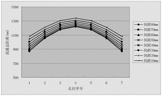
[0038] Embodiment 1, with θ=30, R=100, D=10, 20, 30, 40, 50, 60, 70, 80, the relationship between the total circulation distance L of each hole position and the lens distance D is obtained as follows Figure 5 shown.
Embodiment 2
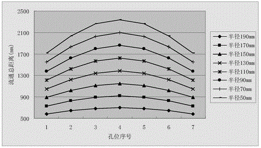
[0039] Embodiment 2, with θ=30, D=50, R=50, 70, 90, 110, 130, 150, 170, 190, the relationship between the total flow distance L of each hole position and the lens radius R is obtained as follows Image 6 shown.
[0040] Combining Embodiment 1 and Embodiment 2, it can be seen that,
[0041] 1. When the lens spacing D changes, the ratio of the total flow distance L of each hole hardly changes, but the radius of the lens changes, and the ratio of the total flow distance L of each hole changes, and the ratio becomes larger with the increase of the radius.
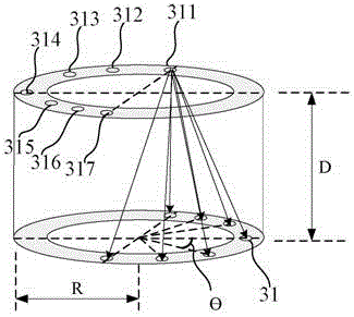
[0042] 2. The air hole 314 at the far end has the longest total flow distance L, and therefore the diameter d of the air hole 314 is the largest.
[0043] Therefore, the final via 31 distribution is as Figure 7 As shown, it should be noted that in the same projection objective, the distance D between the lenses 2 is different, and the radius R of the lens holder 3 is the same. For different projection objectives, the radius ...
PUM
Abstract
The invention discloses a photoetching machine projection objective and an objective support through-hole design method. The photoetching machine projection objective comprises an objective barrel, several objective lenses and lens supports corresponding to the objective lenses. The top of the objective barrel is provided with an air outlet and the bottom of the objective barrel is provided with an air inlet. One side of each one of the lens supports is provided with several through holes. Air flowing amounts and pressure loss values of the through holes are the same. The through holes of the adjacent lens supports are distributed diagonally. According to illumination field cases of each one of the lenses, the different through holes with different pore sizes are arranged at the corresponding lens supports through a specific method and the through holes of the adjacent lens supports are distributed diagonally so that gas pressure stability in a projection objective is guaranteed, full gas communication in the projection objective is realized, heat radiation performances and temperature stability in an optical path area are improved, the optical path area is fully filled with inert gas, projection objective sensitivity to a temperature and pressure is effectively reduced and photoetching quality is improved.
Description
technical field [0001] The invention relates to the field of lithography machines, in particular to a through-hole design method for a projection objective lens of a lithography machine and a lens holder thereof. Background technique [0002] In the optical lithography of large-scale integrated circuits, the resolution of the lithography equipment determines the performance and imaging quality of the lithography machine, and the resolution of the lithography is mainly determined by the resolution of the projection objective lens. With the improvement of the integration of large-scale integrated circuit devices, the requirements for the resolution of the projection objective lens are getting higher and higher. This not only increases the structural complexity of the projection objective lens itself, but also makes its requirements on the ambient temperature and air pressure very strict. . [0003] The stability of the gas pressure inside the projection objective is very impo...
Claims
Application Information
Patent Timeline
Application Date:The date an application was filed.
Publication Date:The date a patent or application was officially published.
First Publication Date:The earliest publication date of a patent with the same application number.
Issue Date:Publication date of the patent grant document.
PCT Entry Date:The Entry date of PCT National Phase.
Estimated Expiry Date:The statutory expiry date of a patent right according to the Patent Law, and it is the longest term of protection that the patent right can achieve without the termination of the patent right due to other reasons(Term extension factor has been taken into account ).
Invalid Date:Actual expiry date is based on effective date or publication date of legal transaction data of invalid patent.
Patent Type & Authority Applications(China)
IPC IPC(8): G03F7/20
Inventor 张洪博赵丹丹聂宏飞龚辉
Owner SHANGHAI MICRO ELECTRONICS EQUIP (GRP) CO LTD