
Roof exhaust pipe fixing device and manufacturing method thereof

A technology for fixing devices and manufacturing methods, applied in roof ventilation, heating methods, household heating, etc., can solve problems affecting the roof, water seepage at the edge of the exhaust pipe, shaking of the exhaust riser, etc., so as to avoid secondary rework and manufacture Convenience and beautiful appearance

Active Publication Date: 2017-12-29
MCC5 GROUP CORP SHANGHAI
View PDF6 Cites 2 Cited by
  • Summary
  • Abstract
  • Description
  • Claims
  • Application Information

AI Technical Summary

Problems solved by technology

During the construction of the roof insulation layer, because the insulation layer is not dry enough or it is difficult to dry, vent holes should be left in the insulation layer during construction of the insulation layer to discharge the moisture in the insulation layer. During construction, due to insufficient fixation of the exhaust pipe, the exhaust riser is displaced and dumped when pouring the thermal insulation protection layer, or the exhaust riser is caused by improper protection of the finished product in the subsequent construction of waterproofing and surface layers. Phenomena such as shaking, skewing, poor combination with the waterproof layer or even damage, etc., lead to the shape of the exhaust pipe, water seepage at the edge of the exhaust pipe, and even affect the waterproof and thermal insulation of the roof, affecting the energy-saving effect of the entire building
[0003] Therefore there are above-mentioned inconveniences and problems in the known roof exhaust pipe setting mode

Method used


Image

  • Roof exhaust pipe fixing device and manufacturing method thereof
  • Roof exhaust pipe fixing device and manufacturing method thereof
  • Roof exhaust pipe fixing device and manufacturing method thereof

Examples


Embodiment 1

[0036] The roof exhaust pipe fixing device of the present invention includes a fixing bracket and a protective cover.

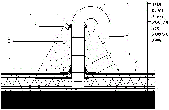
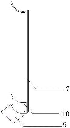
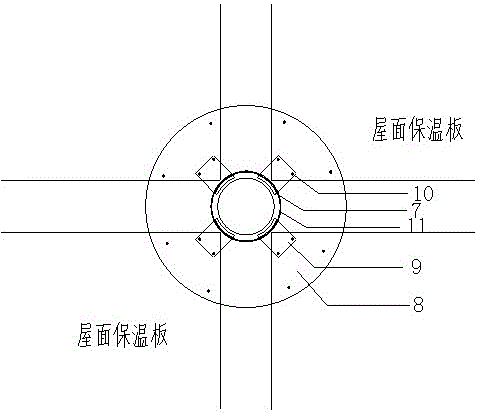
[0037] See now figure 1 with image 3 , figure 1 It is a schematic diagram of the structure and use state of the roof exhaust pipe fixing device of the embodiment of the present invention, image 3 It is a schematic top view of a roof exhaust pipe fixing device according to an embodiment of the present invention. As shown in the figure, the fixing bracket is provided with a base 8 and a set of pillar pieces 7. The base is a circular color steel plate, which is fixed to the roof insulation board with a number of nails 10, and its inner circle diameter is slightly larger than the roof The exhaust pipe has a diameter of 5 to allow the roof exhaust pipe to pass through. The width of the annular color steel plate is 200mm; the set of pillar pieces is provided with four PVC pipe arcs, and the four PVC pipe arcs are equally divided according to the arc of the circle. ...

Embodiment 2

[0040] A method for manufacturing a roof exhaust pipe fixing device, which is characterized by comprising the following steps:

[0041] a. Choose materials

[0042] According to the size and form of the roof exhaust pipe required by the design drawings, the selection includes the PVC pipe used for the fixing bracket, the protective cover steel plate and the plastic tie; the PVC pipe of the roof exhaust pipe fixing device is selected according to Table 1.

[0043] Table 1 Comparison table of PVC pipe size used for roof exhaust pipe and fixing device

[0044]

[0045] b. Make upright pieces

[0046] Choose PVC pipes according to the diameter of the roof exhaust pipes, and cut them into sections according to the exposed height of the roof exhaust pipes. The cut PVC pipe sections are axially sectioned and divided into eight arc-shaped pieces, and 4 pieces are taken to form a set of pillar pieces 7 spare;

[0047] c. Make a base, the base is a ring-shaped steel plate, the ring-shaped steel p...


PUM


Abstract

A roof exhaust pipe fixing device, including a fixing bracket and a protective cover, characterized in that: the fixing bracket is provided with a base (8) and a set of upright pieces (7), the base is a ring-shaped steel plate, and the ring-shaped steel plate is made of several The nails (10) are fixed to the roof insulation board; the set of uprights is provided with four PVC pipe arcs; the protective cover (6) is a round table made of a steel plate, and its lower bottom is set on the exhaust pipe. The decorative surface layer and the protective layer are reserved at the bottom, the upper bottom surrounds the upper part of the exhaust pipe, the inside of the round table is poured with concrete (1), and the top of the round table is coated with sealing paste (4) around the exhaust pipe on the roof. The roof exhaust pipe fixing device of the present invention has the advantages of simple structure, convenient manufacture, good verticality control of roof exhaust holes, beautiful and uniform appearance, preventing damage to PVC pipes, avoiding secondary rework and facilitating follow-up process construction, improving work efficiency, Advantages of saving time.

Description

Technical field [0001] The invention relates to a fixing device, in particular to a roof exhaust pipe fixing device. Background technique [0002] With the continuous development and innovation of the construction industry, the policy of energy saving and consumption reduction has been further strengthened. More and more people have begun to pay attention to building energy saving. The key to reducing building energy consumption is to improve the insulation performance of the maintenance structure. The building envelope has become the carrier of heat transfer and consumption between indoor and outdoor, so the building roof generally adopts an insulation layer formed by insulation materials as a way to save energy and reduce consumption. During the construction of the roof insulation layer, because the insulation layer is not dry enough or it is difficult to dry, vent holes should be left in the insulation layer during the construction of the insulation layer to discharge the mois...

Claims


Application Information

Patent Timeline
Patent Type & Authority Patents(China)
IPC IPC(8): E04D13/17
Inventor 杨明李根张登瑜
Owner MCC5 GROUP CORP SHANGHAI
Learn More