Device and method for preparing high-purity nitrogen and low-purity oxygen

A low-purity, high-purity technology, applied in refrigeration and liquefaction, lighting and heating equipment, liquefaction, etc., can solve problems such as energy waste, and achieve the effects of reducing production costs, objective economic benefits, and significant economic and social benefits

Active Publication Date: 2016-07-13
HENAN KAIYUAN AIR SEPARATION GRP CO LTD
View PDF7 Cites 1 Cited by
  • Summary
  • Abstract
  • Description
  • Claims
  • Application Information

AI Technical Summary

Problems solved by technology

[0004] The technical problem to be solved by the present invention is: in order to overcome the deficiency of energy waste caused by the venting of low-concentration oxygen in the preparation process of the existing high-purity nitrogen device, the present invention provides a device for producing high-purity nitrogen and low-purity oxygen by using air and method

Method used


Image

  • Device and method for preparing high-purity nitrogen and low-purity oxygen

Examples


Embodiment 1

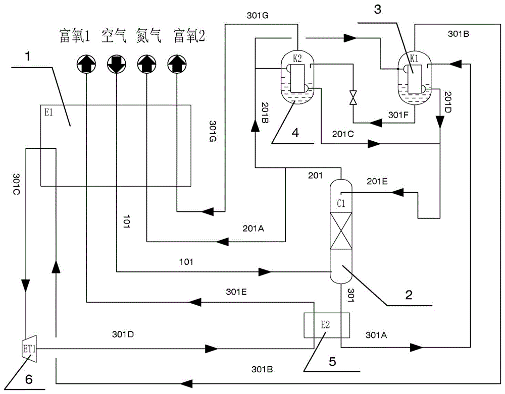
[0036] The outlet of oxygen-enriched liquid air at the bottom of rectification tower C1 is connected with the inlet of oxygen-enriched liquid air of subcooler E2 through pipeline 301, and the outlet of oxygen-enriched liquid air of subcooler E2 is connected with the inlet of oxygen-enriched liquid air of condenser K1 through pipeline 301A; The oxygen-enriched waste gas outlet of K1 is connected to the oxygen-enriched waste gas inlet of the main heat exchanger E1 through the 301B pipe, and the oxygen-enriched waste gas outlet of the main heat exchanger E1 is connected to the oxygen-enriched waste gas inlet of the turbo expander ET1 through the 301C pipe. The oxygen-enriched exhaust gas outlet is connected to the oxygen-enriched exhaust gas inlet of the subcooler E2 through the 301D pipeline, and the oxygen-enriched exhaust gas outlet of the subcooler E2 is connected to the oxygen-enriched gas 1 inlet of the main heat exchanger E1 through the 301E pipeline, and the oxygen-enriched g...

Embodiment 2

[0042] b. The air cooled by the main heat exchanger E1 in step a enters the rectification tower C1 from the lower part of the rectification tower C1 through the 101 pipeline (the rectification tower adopts a plate rectification tower) for rectification and separation, and after separation, the rectification tower C1 High-purity nitrogen is obtained at the top (the purity of high-purity nitrogen is ≥99.9995%), and oxygen-enriched liquid air is obtained at the bottom; among the obtained high-purity nitrogen, the high-purity nitrogen product enters the main heat exchanger E1 through pipeline 201 and pipeline 201A, and is reheated Send and collect at room temperature to obtain high-purity nitrogen products (purity of high-purity nitrogen ≥ 99.9995%); the remaining high-purity nitrogen ascending gas enters condenser K2 and condenser K1 respectively through pipeline 201 and pipeline 201B, and is condensed into liquid nitrogen , the condensed liquid nitrogen is collected in the 201E p...

Embodiment 3

[0047] In step d: the oxygen-enriched gas product 2 is obtained, the purity of the obtained oxygen-enriched gas product 2 reaches 47%, and the pressure p reaches 0.23 MPa.

[0048] Embodiment 4: basically the same as Embodiment 2, the difference is:

[0049] In step c: the oxygen-enriched liquid air is evaporated in K1 with an evaporation rate of 70%; the oxygen-enriched gas product 1 is obtained (the product has a purity of 29% and a pressure of 11KPa);


PUM


Abstract

The invention discloses a device and a method for preparing high-purity nitrogen and low-purity oxygen. The device comprises a main heat exchanger, a rectification tower, two condensers, a supercooler and a turbine expander which are communicated through pipelines. The method includes that air in atmosphere enters the main heat exchanger for cooling after being compressed, filtered and purified, and then enters the rectification tower for separation, and high-purity nitrogen and oxygen-rich liquid air are obtained at the top and the bottom of the rectification tower respectively after separation; part of the high-purity nitrogen obtained is reheated through the main heat exchanger to normal temperature to be fed out for collection, and the rest of the high-purity nitrogen is condensed into liquid nitrogen through the condensers to serve as reflow liquid; two oxygen-rich gas products are obtained after the oxygen-rich liquid air is sequentially treated with the supercooler, the condensers, the expander and the main heat exchanger. By using the device and the method, the high-purity nitrogen can be obtained, and oxygen-rich products different in purity and pressure and high in oxygen purity can be obtained. The device can run in multiple working conditions, so that needs of the oxygen-rich products different in purity and pressure are met.

Description

technical field [0001] The invention belongs to the technical field of gas separation methods and devices, in particular to a device and method for producing high-purity nitrogen and low-purity oxygen from air. Background technique [0002] Safety and reliability, energy saving and emission reduction are the basic requirements and prerequisites for air separation equipment, the needs of building a resource-saving and environment-friendly society and scientific development, and also market expectations. Both the emerging coal chemical industry and the mature iron and steel metallurgy industry need a large amount of low-purity oxygen. In order to protect the environment and capture carbon dioxide, oxygen-enriched combustion has also become a trend in the development of power plants. [0003] In the current high-purity nitrogen plant, while producing high-purity nitrogen, the by-product is low-purity oxygen-enriched. Usually, since the oxygen content of this part of the gas i...

Claims


Application Information

Patent Timeline
Patent Type & Authority Applications(China)
IPC IPC(8): F25J3/04
CPCF25J3/04284F25J3/0423F25J3/044F25J2200/72F25J2250/10F25J2250/20F25J3/04054F25J2210/40
Inventor 张世田贾军彭明扬
Owner HENAN KAIYUAN AIR SEPARATION GRP CO LTD
Why Eureka
Try Eureka