Intelligent photoelectric composite cable for monitoring local large deformation of structure and monitoring method

A photoelectric composite cable and large deformation technology, which is applied in the direction of insulated cables, communication cables, cables, etc., can solve the problems of difficult strain range, damage sensitivity, lack of suitable means for monitoring large local deformation of the structure, etc., and achieve the sensing transmission line Simple, highly operable, and saves layout costs

Inactive Publication Date: 2016-07-20
DALIAN UNIV OF TECH
View PDF3 Cites 12 Cited by
  • Summary
  • Abstract
  • Description
  • Claims
  • Application Information

AI Technical Summary

Problems solved by technology

However, the strain caused by the local large deformation of the structure can reach more than 10%, which is far beyond the deformation capacity of the glass optical fiber. At the same time, it is prone to shear brittle fracture. More than 20,000 microstrains
Although plastic optical fiber exhibits good characteristics of high ductility and large strain, up to about 15%, commercialized plastic optical fiber is mainly multimode optical fiber, and dispersion and multimode interference restrict the distributed sensing ability of this technology
In addition, some people have preliminarily realized the real-time monitoring of local cracks in the structure with the help of electrical time domain reflection technology of high-

Method used


Image

  • Intelligent photoelectric composite cable for monitoring local large deformation of structure and monitoring method
  • Intelligent photoelectric composite cable for monitoring local large deformation of structure and monitoring method
  • Intelligent photoelectric composite cable for monitoring local large deformation of structure and monitoring method

Examples


specific Embodiment approach

[0026] (1) Intelligent photoelectric composite cable

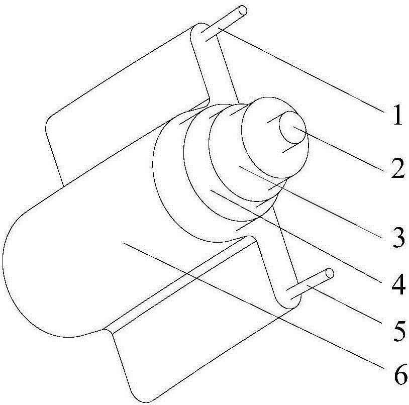
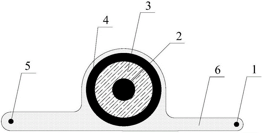
[0027] The main structure of the intelligent photoelectric composite cable of the present invention is as follows: figure 1 and figure 2 shown. The optical fiber 1 and optical fiber 5 written into the grating and the coaxial cable composed of the inner conductor 2, the insulating layer 3 and the outer conductor 4 are wrapped and compounded by room temperature curing silicone rubber 6 to form a distributed sensing cable that works together. For the functions of different sensing probes, the thickness of the silicone rubber 6 needs to be considered: considering the strain transfer analysis, the average thickness of the packaging layer should be less than 1.5mm.

[0028] The main steps of the manufacturing process of the intelligent photoelectric composite cable are as follows: firstly, the optical fiber 1 and the optical fiber 5 are peeled off the coating layer and cleaned with alcohol; secondly, the coaxial cable Fabry-P...


PUM

PropertyMeasurementUnit
Thicknessaaaaaaaaaa

Abstract

The invention discloses an intelligent photoelectric composite cable for monitoring local large deformation of a structure and a monitoring method. The intelligent photoelectric composite cable comprises distributed sensing devices capable of working together, wherein the distributed sensing devices are formed by compounding two sensing probes of an optical fiber and a coaxial cable employing silicone rubber as a cohering and filling medium and customizing a strain measurement gauge length in advance; various strains and temperature sensing probes are connected to an ROTOR demodulator, an FBG demodulator, a BOTDA/Rdemodulator and a CCFPI demodulator through transmission cables respectively; and strain data of a strain sensing array after temperature compensation correction is obtained, so that whole-process monitoring of the local large deformation of the structure is achieved. Aiming at the condition that an existing test method cannot easily track damage information of the local large deformation process of the structure, the bottleneck problem of combination of micro high precision and a macro large strain test is solved by the intelligent photoelectric composite cable; and a distributed optical fiber sensing technology and a distributed coaxial cable sensing technology are merged for the first time to construct an intelligent monitoring system.

Description

technical field [0001] The invention belongs to the technical field of structural health monitoring and modern detection, and relates to an intelligent photoelectric composite cable and a monitoring method for monitoring local large deformation of a structure. Background technique [0002] Large local deformation of structures (mainly manifested as localized large strains) is an important cause of structural failure and damage, and its behavior often manifests as strong nonlinearity (geometric or material nonlinearity) and strong coupling effects. The whole process test of the local large deformation of the structure can provide technical support for the scientific understanding of the failure mechanism, the design of the structural behavior and the evaluation of the safety state. [0003] The overall performance monitoring of structures generally adopts displacement sensors such as velocity and accelerometers. When a material or component partially enters the nonlinear lar...

Claims


Application Information

Patent Timeline
IPC IPC(8): H01B11/22H01B7/02H01B7/17H01B7/18H01B7/24H01B7/28H01B7/282G01B11/16
CPCG01B11/16H01B7/0275H01B7/17H01B7/187H01B7/24H01B7/2806H01B7/2825H01B11/22
Inventor 周智任鹏欧进萍
Owner DALIAN UNIV OF TECH
Why Eureka
Try Eureka